Need help with fuzz face wiring

PAGOON

Active member
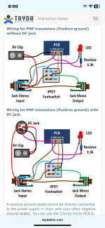
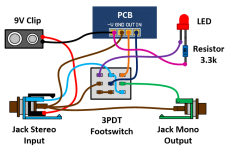
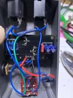
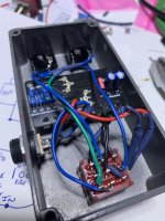
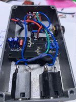
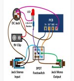
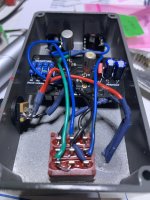
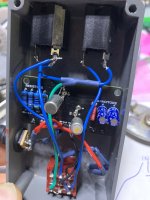
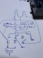
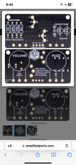
I am using a mod electronics pcb .. I wired it up using this diagram I didn’t hook us the 9v battery harness..the pedal isn’t working a really low i distorted sound can be heard if the amp’s volume is turned way up.. and I noticed on q3 there was continuity from the positive and negative side of that capacitor, which I think that may be normal but I’m not 100% sure
 

Attachments

  • image.jpg
    image.jpg
    382.9 KB · Views: 20
  • image.jpg
    image.jpg
    424.6 KB · Views: 21
  • image.jpg
    image.jpg
    401.5 KB · Views: 20
  • IMG_1060.png
    IMG_1060.png
    527 KB · Views: 22
  • IMG_1061.jpeg
    IMG_1061.jpeg
    77.4 KB · Views: 21
  • IMG_1062.jpeg
    IMG_1062.jpeg
    432.7 KB · Views: 18
  • IMG_1063.jpeg
    IMG_1063.jpeg
    353.9 KB · Views: 14
  • image.jpg
    image.jpg
    249.2 KB · Views: 13
  • IMG_1050.png
    IMG_1050.png
    2.2 MB · Views: 16
Last edited:
A little hard to tell from the photos but it looks like you have the power connected backwards. Center should be the -9V rail and sleeve should be ground.
That’s what I’m thinking as well I found a better diagram that shows a better picture of that 9v female jack… I took this from tayda..ALSO WHAT HAS CONFUSED ME IS THE LED PICTURE THE FLAT SIDE IS THE CATHODE IN THE PICTURE BUT ITS DRAWN WITH A LONGER TERMINAL WHICH IS WEONG OR JUST CONFUSING… but I feel I’m getting closer to finding this out thank you for your help analog device I appreciate your input.. thank you
 

Attachments

  • IMG_1066.png
    IMG_1066.png
    319.8 KB · Views: 7
  • IMG_1064.png
    IMG_1064.png
    73.9 KB · Views: 7
the way the led is drawn is a bit confusing, but if I'm reading things right there's a little line to show where the led lead ends and the resistor lead begins. I know having the resistor for the led is kinda traditional (tho a vintage acurate fuzz face doesn't have an led) but this is one of the many reasons I prefer having the led resistor on the pcb.
 
Back
Top