Octagon- Dry signal present, no modulation

Pauleo1214

Well-known member
I'm baffled and don't know where to start on this one. Here is what I know.

1. The dry signal is present and clear and affected by the volume and mix knobs.
2. The EEPROM chip is likely not the issue. I took a working EEPROM from my Daydream Delay and popped in it and got the same result.

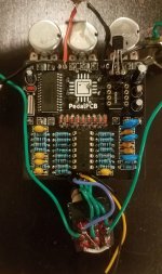
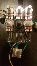
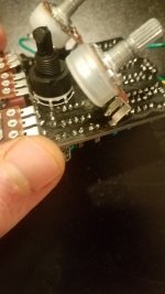
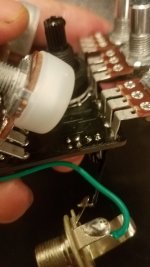
I am posting pics below (Please note the EEPROM is removed in the photos and not at the time of testing the pedal). Does anyone know where I might start troubleshooting this board? Thank you!

20210531_023037.jpg
20210531_022811.jpg
20210531_022914.jpg
20210531_022925.jpg
 
Did you solder the FV1 yourself? Did you check all of your resistor and cap values?

You can jumper pin13 to ground on the FV1 test if that is working.

Thanks for your reply. I bought the board with the FV-1 pre-soldered. One of these days I will have to test my hands with surface mount soldering.

Did not check my resistor or cap values yet, but that is on my to do list tomorrow night. Jumpering pin 13 go ground is also now added. I am certain the values are correct but I've made (many) mistakes before.

Unless I am wrong, my thinking was an incorrect value would keep modulation from occurring.
The pictures were a bit blurry but your joints look good. It can be worth reflowing them to make sure there isn’t a cold joint.

If t you get the internal settings working from the FV1 then I assume there could be a cold joint or an incorrect value in the wet side of the circuit in blue.

I hope you get it working! 👍🏻
 

Attachments

  • 626F6661-CD90-44F7-B2A1-C723DC2D3EA6.jpeg
    626F6661-CD90-44F7-B2A1-C723DC2D3EA6.jpeg
    116.5 KB · Views: 4
Thanks Jamie! Apologies for the blurry pics, I really need to update my phone!

I put a jumper to pin 13 to ground but no wet signal came through. Pardon the dumb question, what else do I need to look out for when testing the FV-1 with the jumper?

I am going to re-check all my components next.

Best,

Paul
 
By having pin 13 to ground it stops the connection to the EEPROM so it should then give you the internal wet signal from the chip. Try rotating the selector pot all the way to the left - that should be a chorus-reverb sound. If you aren’t getting that then it could be the FV1 that is the issue.

Have you got a DMM?
 
Update:

I checked all my resistors; all were the correct values except R18 and R22. Turns out my bag of 1K resistors were mislabeled and were 1M.

The effect works except the volume of the wet signal is very low and there is a static sound similar to being inside with hard wind blowing against a building (no high pitched whistling). I suspect I have a wrong value capacitor somewhere in the wet signal path. .
 
By having pin 13 to ground it stops the connection to the EEPROM so it should then give you the internal wet signal from the chip. Try rotating the selector pot all the way to the left - that should be a chorus-reverb sound. If you aren’t getting that then it could be the FV1 that is the issue.

Have you got a DMM?
I do have a DMM.
 
1K = Brown, Black, Black, Brown, Brown
R3 & R18 look incorrect!
I can't believe I am making these dumb mistakes.

I am not sure if I will be able to repair the pedal now. The mix potentiometer broke due to metal fatigue. I tore out a couple of the pcb pads ( (and possibly tracks) removing the solder pins.
 
I can't believe I am making these dumb mistakes.

I am not sure if I will be able to repair the pedal now. The mix potentiometer broke due to metal fatigue. I tore out a couple of the pcb pads ( (and possibly tracks) removing the solder pins.
The pot should be easily dealt with - you can just wire it in.

It may be possible to jumper some of the pads. Put some picture on here for the forum fairy’s to sprinkle their magic.
 
I can't believe I am making these dumb mistakes.

I am not sure if I will be able to repair the pedal now. The mix potentiometer broke due to metal fatigue. I tore out a couple of the pcb pads ( (and possibly tracks) removing the solder pins.

Because of hidden traces, check to see if the Resistors with matching colours have Continuity with each other first!
If they are correct, they go to the matching colour on the Mix legs.
Did all 3 pads get destroyed ? :

Octagon Continuity Test.jpg
 
Last edited:
Pardon the delayed reply; Thank you Jamie and Music6K for your continued help!

Lugs 3 and 2 are destroyed. I do get continuity from 1 to the sides of R19 and R21 (thank you for the photo Music6K).

My next order of business right now is remove R3 and R18 and replace with 1K resistors, then wire jumpers from lugs 2 and 3.
Ar you getting Continuity between R20 & R4 in Red?
 
UPDATE: R3 and R18 are replaced with 1K resistors. I also wired jumpers from Lug 2 of the blend pot to the right side of R6. I wired another jumper from lug 3 of the blend pot to the left sides of R20 and R4.

The effect is now working, the output is quite high however and the dry signal has a fair amount of dirt (which sounds quite good, actually). I'm going to box it up and not mess with it anymore for fear ofr damaging the board further! Jamie and Music6000, thank you! I greatly appreciate your help!
 
Last edited:
The jumper should go from Leg 3 to Right side of R20 which is connected to R4 which is why it has continuity.
The Picture of PCB above has been corrected, Then your pedal should work as intended.
 
Apologies.
1, Confirm continuity between R21 and R19 in blue.
2. No continuity between R20 and R4 on the left side pcb pads that are highlighted in red. I do get continuity if I touch the right sides of R4 and R20..
The jumper should go from Leg 3 to Right side of R20 which is connected to R4 which is why it has continuity.
The Picture of PCB above has been corrected, Then your pedal should work as intended.
 
Back
Top