Cybercow
Well-known member
We've been wanting a 1-of-4 switching solution for our RMS X100 V3 pedal so the user could select any one of the four basic preamp Modes on this pedal. For this version of the RMS X100 V3 we wanted one stompswitch per mode option with no bypass switch.
Earlier this year, our esteemed team leader found this schematic from an old DIY forum post to work from . . . .

After trying this out on a breadboard, it was found wanting in a couple of points.
1) It has no switch-debounce and the logic did not always hold when a switch was selected.
2) Boot-up is inconsistent and does not always boot-up in the same logic state.
After futzing with it on the breadboard . . . .

I was able to achieve solid switching action by adding a 100nF cap to each of the momentary-on switches pull-down resistors.
And a consistent boot-up default state was achieved by adding a clamping diode to one of the switches.
As for power supply, I found that this circuit works best at least +9V. Below 8 volts the logic outputs and LEDs begin to exhibit threshold operation. So, 9V seems to be ideal.
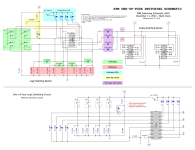
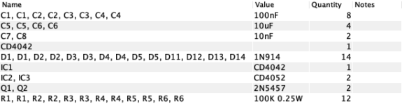
Here is the final schematic in generic format for anyone who wishes to pursue a similar solution. It can also be used for a 1-of-3 switching solution by omitting switch #4 - but leaving in tact the switch #4 pull-down & debounce cap.

Hope someone finds this useful.
Earlier this year, our esteemed team leader found this schematic from an old DIY forum post to work from . . . .

After trying this out on a breadboard, it was found wanting in a couple of points.
1) It has no switch-debounce and the logic did not always hold when a switch was selected.
2) Boot-up is inconsistent and does not always boot-up in the same logic state.
After futzing with it on the breadboard . . . .

I was able to achieve solid switching action by adding a 100nF cap to each of the momentary-on switches pull-down resistors.
And a consistent boot-up default state was achieved by adding a clamping diode to one of the switches.
As for power supply, I found that this circuit works best at least +9V. Below 8 volts the logic outputs and LEDs begin to exhibit threshold operation. So, 9V seems to be ideal.
Here is the final schematic in generic format for anyone who wishes to pursue a similar solution. It can also be used for a 1-of-3 switching solution by omitting switch #4 - but leaving in tact the switch #4 pull-down & debounce cap.

Hope someone finds this useful.
Last edited: