Park and ride, signal not getting through

borntohula1993

New member
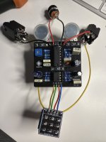
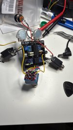
Hey everyone, first time posting. Second time building a diy pedal after a successful octave fuzz. Trying my hand at the park and ride fixed wah. Really need help. Started out completely fine, started getting weird pulses, realised my 16 and 8 pins were in the wrong way.. (didn’t think the direction mattered for some reason). Besides that, I’ve been very careful sticking to the schematic. Once that was fixed I got 9 volts running to it and seeming ok on multimeter. Current issue: When I switch it on, my guitar signal drops out entirely, but I can hear sweeping midrangey sounds, buzz volume changes etc when I play with the pots (as if the circuit is working but the guitar signal is just not getting through). Started blaming the daughter board so I took it off and tried wiring it as per the old schematic on the product page. Same thing. Pretty confident I’ve now destroyed my daughter board, ruined my switch and and left with an undiagnosed problem that is probably so simple and obvious to a more experienced builder. See attached pics, ignore incorrect orientation of my TL0s in the first pic. Any help greatly appreciated! IMG_35D8F82C-6FD0-4CF1-96E2-6F7BA0F67D89.jpeg 14BFD743-EB40-4620-A1DD-00F1A2184DAB.jpeg
 
Welcome aboard!
Are those opamps in the correct orientation? Pin 1 should be at upper left.
The film cap values look ok. Verify your resistor values, the colors are always hard to read properly from a photo (at least for my eyes).
Also verify the pot values.
And send a good pic of the lower side, so we can look for bad solder joints.
 
Works in bypass?
Do you have spare opamps?
Do you have a DMM to test the switch? It has seen some heat.
Works in bypass, yep. If I bypass the switch now with a wire from in to out I can hear the pots doing their thing faintly over the hum when I turn them.
No spare op amps.. could have fried them when they were in the wrong position?
Switch is definitely ruined, ordered fresh one for tomorrow
 
Welcome aboard!
Are those opamps in the correct orientation? Pin 1 should be at upper left.
The film cap values look ok. Verify your resistor values, the colors are always hard to read properly from a photo (at least for my eyes).
Also verify the pot values.
And send a good pic of the lower side, so we can look for bad solder joints.
The whole board is starting to look like a melted slab of caramel.. you can see my desperation. I’ve gone over the solder joints a few times now. Jokes aside I’ve been careful not to overheat anything
 

Attachments

  • image.jpg
    image.jpg
    960.5 KB · Views: 16
Is there a bridge to the right leg of the bottom pot? Looks like the component leg may be touching the pot leg.

Could have fried the opamps. Could be a bad resistor value or cold solder joint/bridge.
Assuming you can't count resistor bands, find a well lit build report and compare the resistor bands in those photos and your build.
 
If you have a DMM, measure each leg of the opamps vs ground and post the results. I.e.
Pin 1: x.x
Pin 2 x.x
Seems I may have cooked the 8 pin, here’s v for each each pin with my black probe on ground. Do these values mean the 14 pin survived?

Pin 1: 0
Pin 2: 0
Pin 3: 4.08
Pin 4: 0
Pin 5: 4.5
Pin 6: 3.7
Pin 7: 3.7
Pin 8: 9
This is on the 8 pin

For the 14 pin
1 4.5
2 4.5
3 4.5
4 9
5 4.5
6 4.5
7 4.5
8 4.5
9 4.5
10 4.5
11 0
12 4.5
13 4.5
14 4.5
 
Both your op amps were installed upside down on the first picture.

A notch in the center of one edge or dot closer to one side than the other typically denotes where pin 1 of the IC is located.

On the PCB for an IC, the silk screen image will typically have the notch and pin 1 will be a square pad instead of a circular pad like the rest of the pins.
I’ve definitely fried them! The 16 pin got warm, the 8 pin is giving dodgy readings. But now I’ve got New ones ordered and you helpful people on standby to make sure I don’t mess it up again :)
 
I’ve definitely fried them! The 16 pin got warm, the 8 pin is giving dodgy readings. But now I’ve got New ones ordered and you helpful people on standby to make sure I don’t mess it up again :)
It's all part of the process... Make sure to order a handful of ICs instead of just one or two. I typically get 10 to 20 op amps each time I do an order.
 
Yeah - TL072s are relatively cheap in quantity and they're in almost every pedal. And if they're not in the pedal, a lot of the time they can be subbed for whatever opamp anyway - dual opamps have a standard pinout so things that call for NE5532, RC4558, etc can generally at least function with a TL072 in there. (But honestly those particular chips are cheap as well, just get a pile of them). In qty10, Mouser in the USA is
TL072: ~0.70
RC4558: ~0.25
NE5532: ~0.50

TL074s are a little less common - most pedals do a couple dual opamps instead of a quad but even still, worth picking up some extras. Those are even cheaper than the TL072s at Mouser somehow.
 
Back
Top