
You are using an out of date browser. It may not display this or other websites correctly.
You should upgrade or use an alternative browser.
You should upgrade or use an alternative browser.
Parts Layout and Drill Template with Eagle Cad
- Thread starter hpdonat
- Start date
jessenator
Well-known member
I'm resisting KiCad and sticking with Eagle as long as I can : P It's what I learned on.
But to your question, I do use it for the top control drill template. I do a lot of custom designs, but I've also made a few that match the PedalPCB Tayda drill patterns (again, only the top). For back side drilling (jacks and DC) I do all of the measurements in 3D, but I'm going to standardize that so I can use the Eagle enclosure footprints for drill templating.
I've borrowedquite a bit everything from Madbean's Eagle Library, and I've also added in some custom bits here and there. Here's a couple set up for 3 and 4 knob configurations (PPCB patterns)


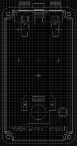
And one for my 1590B3 adventuresL:

My other custom ones are sort of arbitrary, and followed a very inconsistent pattern.
Anyhow, that's how I do. Still using Eagle (and in mils, no less)
edit: the footswitch drill position varies, depending on the board size. I like to keep it away from the extreme end, so that diagram is adjustable.
Edit 2: up till about now, I've used Illustrator to do everything short of the schematic and board layout. It's nice to have the art, hardware, and drill patterns all in one file on respective layers. I still will use illustrator for the art, but for boards that aren't my own, I'll use their drill patterns (obvs). Still, all in one place in convenient.
But to your question, I do use it for the top control drill template. I do a lot of custom designs, but I've also made a few that match the PedalPCB Tayda drill patterns (again, only the top). For back side drilling (jacks and DC) I do all of the measurements in 3D, but I'm going to standardize that so I can use the Eagle enclosure footprints for drill templating.
I've borrowed

And one for my 1590B3 adventuresL:

My other custom ones are sort of arbitrary, and followed a very inconsistent pattern.
Anyhow, that's how I do. Still using Eagle (and in mils, no less)
edit: the footswitch drill position varies, depending on the board size. I like to keep it away from the extreme end, so that diagram is adjustable.
Edit 2: up till about now, I've used Illustrator to do everything short of the schematic and board layout. It's nice to have the art, hardware, and drill patterns all in one file on respective layers. I still will use illustrator for the art, but for boards that aren't my own, I'll use their drill patterns (obvs). Still, all in one place in convenient.
Attachments
Last edited:
KR Sound
Well-known member
I need to make these for KiCad! Or find some DXF files of these.I'm resisting KiCad and sticking with Eagle as long as I can : P It's what I learned on.
But to your question, I do use it for the top control drill template. I do a lot of custom designs, but I've also made a few that match the PedalPCB Tayda drill patterns (again, only the top). For back side drilling (jacks and DC) I do all of the measurements in 3D, but I'm going to standardize that so I can use the Eagle enclosure footprints for drill templating.
I've borrowed quite a bit from Madbean's Eagle Library, but I've also added in some custom bits. Here's a couple set up for 3 and 4 knob configurations (PPCB patterns)
View attachment 69332
And one for my 1590B3 adventuresL:
View attachment 69334
My other custom ones are sort of arbitrary, and followed a very inconsistent pattern.
Anyhow, that's how I do. Still using Eagle (and in mils, no less)
edit: the footswitch drill position varies, depending on the board size. I like to keep it away from the extreme end, so that diagram is adjustable.
Edit 2: up till about now, I've used Illustrator to do everything short of the schematic and board layout. It's nice to have the art, hardware, and drill patterns all in one file on respective layers. I still will use illustrator for the art, but for boards that aren't my own, I'll use their drill patterns (obvs). Still, all in one place in convenient.
jessenator
Well-known member
Updated the language in my post; didn't give enough credit to Bean.
I'm weird and I made a library from the Hammond engineering PDFs. However, they aren't all 100% scale.
I'm weird and I made a library from the Hammond engineering PDFs. However, they aren't all 100% scale.
If you want, I have DXFs exported from Illustrator for all of the (main) Hammond 1590 series enclosure outlines. I can put them up on Dropbox.I need to make these for KiCad! Or find some DXF files of these.
jessenator
Well-known member
let me know if these work. They are 1:1 scaled in mm (if that's important to the DXF import).I need to make these for KiCad! Or find some DXF files of these.
KR Sound
Well-known member
Awesome- thanks!let me know if these work. They are 1:1 scaled in mm (if that's important to the DXF import).