- Build Rating
- 3.00 star(s)
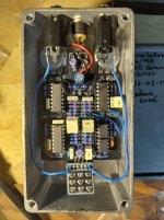
My first post almost ended up being one of the trouble shooting cries for help. When I first put this pedal together and tested it, I only got the dry signal on the phaser side, and no signal at all on the vibrato side. I also started to notice the smell of something burning, and found ic2 burning hot.
A little bit of DMM investigation later tracked down a short to ground in the node connecting R22, R21, C7, and pin 9 of ic2. All the solder points looked ok, and I couldn't see any obvious damage to the pcb.
I had, initially planned to ask for help here, but being impatient I just started to disassemble the mentioned parts instead. When I finally removed the pin of the ic (just pulled the clip side out with a a pair of pliers while de-soldering the underside), the short disappeared.
Anyway, that's why some of the soldering looks like crap and the ic is connected to R21 using a cable. To make things even more chaotic, C7 is mounted on the other side of the PCB since my 1uF caps were the wrong size.
The build is just a stock Circulator. I ordered the entire kit through musikding, and other than the wrong size caps and a missing ic, it's almost paint by numbers with well marked components sorted into their own little bags.
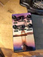
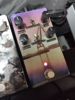
The graphics is a picture I took of the harbor here in Gothenburg with some old slide film I found, which I then developed in some regular C-41 negative film chemistry. Which I then used to design the fancy image you see. I finally found somewhere to order UV DTF prints at a reasonable cost.
It is a rather tight build component wise. Not a big problem when putting it together, but it does complicate things when trying to de-solder.
Sound wise I haven't really spent enough time with it to understand it yet. The span of sounds you can dial in is huge. I not sure all of them are that useful, but once you find a sweet spot, it is some kind of swirly, pulsating, wonderful madness that I'm starting to get real fond of. I'm planning to keep it on my board until I either figure out what I want if for, or rather, if I want the lovely magical madness that comes out of it.
A little bit of DMM investigation later tracked down a short to ground in the node connecting R22, R21, C7, and pin 9 of ic2. All the solder points looked ok, and I couldn't see any obvious damage to the pcb.
I had, initially planned to ask for help here, but being impatient I just started to disassemble the mentioned parts instead. When I finally removed the pin of the ic (just pulled the clip side out with a a pair of pliers while de-soldering the underside), the short disappeared.
Anyway, that's why some of the soldering looks like crap and the ic is connected to R21 using a cable. To make things even more chaotic, C7 is mounted on the other side of the PCB since my 1uF caps were the wrong size.
The build is just a stock Circulator. I ordered the entire kit through musikding, and other than the wrong size caps and a missing ic, it's almost paint by numbers with well marked components sorted into their own little bags.
The graphics is a picture I took of the harbor here in Gothenburg with some old slide film I found, which I then developed in some regular C-41 negative film chemistry. Which I then used to design the fancy image you see. I finally found somewhere to order UV DTF prints at a reasonable cost.
It is a rather tight build component wise. Not a big problem when putting it together, but it does complicate things when trying to de-solder.
Sound wise I haven't really spent enough time with it to understand it yet. The span of sounds you can dial in is huge. I not sure all of them are that useful, but once you find a sweet spot, it is some kind of swirly, pulsating, wonderful madness that I'm starting to get real fond of. I'm planning to keep it on my board until I either figure out what I want if for, or rather, if I want the lovely magical madness that comes out of it.
Attachments
Last edited:
") , this pedal is on my list to build someday.
, this pedal is on my list to build someday.