BuddytheReow
Moderator
For those of you who are fuzz junkies, the PPCB Percolation Station (Harmonic Percolator) is one of the more unique fuzzes out there using a 2 transistors (Q1 is germanium and Q2 is silicon) that feed into each other and make something very different sonically. Here is a breadboard tutorial for those of you that are interested. I will be using the PPCB Percolation Station schematic along with the PPCB Protoboard.

And the final build. Let's get started!

Alright, first thing's first. Let's get that power section out of the way. I chose to not install D100 since that is for polarity protection and I know that my power is hooked up correctly. All you need to do is throw C100 directly into the power rails to "clean up" the incoming power. IMO this is a noisy circuit so every bit helps here. I've also decided to keep a LED and 4.7k resistor more permanently on my board as a power indicator. This piece is optional, but you can add if you like.

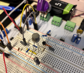
OK, now it's time for the main circuit. INPUT goes directly into pin 3 of the HARMONICS pot, pin 1 to ground and pin 2 to the next stage. That red jumper in the pic is my input and the orange/white (blurry) are my power cables. Simple enough, right? Out of pin 2 we need to add C1 which removes some of the super highs. This goes to ground.

I will start with Q1 as per the schematic and then work my way to Q2. C2 has a value of 50n so I used a 47n. 47n is a much more common value today. Close enough. I also need to mind the pinout of Q2 (PNP). In my pic going left to right is C-B-E.

In the above pic you can see that C2 is not connected to Q1 yet. A simple jumper will fix that. I decided to spread out a bit more than I usually do to have more breathing room and also get some better pics. My camera phone is a PITA sometimes, but you get the idea. I also install R4 with goes from collector to ground and R2 which connects collector to base of Q1. This helps bias the transistor. That extra leg sticking out of Q2 you can just ignore since it's not used here.

OK. Let's start working our way up (literally) to mimic the schematic. Both emitters are connected together with an additional bypass capacitor going to ground (C4). Q2 in the pic below has a pinout going left to right of C-B-E. I decided to throw a jumper from the collector to C6 since I know that's the "end" stage of this circuit block and something to work towards.

So, a little hard to tell from my pic, but we now need to install R3 to give both transistors some power and also R1 to bias Q2. R1 is connecting collector to base. R3 is going from the power rails to the collector of Q2. Now the "odd" part of this breadboard build. We need to install C3 which connects the base of Q2 to the emitter of Q1. If you're referencing the schematic you will notice that there is no "dot" when the input to Q2 base and C3 connection. This means that these 2 do not connect to each other and you should consider them separate connections. I've highlighted the missing "dot" below. Other connections DO have this "dot".


After C6, we need to add our hard clipping diodes to ground. One of them (it doesn't matter which) needs to have R5 going in series before going to ground. I chose to use D9K germanium diodes with a voltage drop of approx 460mV. I also install a jumper so we can hook this up to the BALANCE control before going to output.

Last, but not least the BALANCE control. It's just a volume knob in standard voltage divider format. Pin 3 to the diodes, pin 1 to ground, and pin 2 to output.

And there you have it. The PPCB Percolation Station! If you're a fan of chugs of sixteenth note palm mutes, this circuit isn't for you. This is a creamy, 8-Bit sounding fuzz with a ton of harmonics thrown in there. IMO, the circuit sounds best with the BALANCE control at max and this control is done better via your guitar's volume knob. This circuit is definitely a "try it out" on a breadboard before committing to solder. Transistor and diode selection is key here and is worth your time experimenting on.

And the final build. Let's get started!

Alright, first thing's first. Let's get that power section out of the way. I chose to not install D100 since that is for polarity protection and I know that my power is hooked up correctly. All you need to do is throw C100 directly into the power rails to "clean up" the incoming power. IMO this is a noisy circuit so every bit helps here. I've also decided to keep a LED and 4.7k resistor more permanently on my board as a power indicator. This piece is optional, but you can add if you like.

OK, now it's time for the main circuit. INPUT goes directly into pin 3 of the HARMONICS pot, pin 1 to ground and pin 2 to the next stage. That red jumper in the pic is my input and the orange/white (blurry) are my power cables. Simple enough, right? Out of pin 2 we need to add C1 which removes some of the super highs. This goes to ground.

I will start with Q1 as per the schematic and then work my way to Q2. C2 has a value of 50n so I used a 47n. 47n is a much more common value today. Close enough. I also need to mind the pinout of Q2 (PNP). In my pic going left to right is C-B-E.

In the above pic you can see that C2 is not connected to Q1 yet. A simple jumper will fix that. I decided to spread out a bit more than I usually do to have more breathing room and also get some better pics. My camera phone is a PITA sometimes, but you get the idea. I also install R4 with goes from collector to ground and R2 which connects collector to base of Q1. This helps bias the transistor. That extra leg sticking out of Q2 you can just ignore since it's not used here.

OK. Let's start working our way up (literally) to mimic the schematic. Both emitters are connected together with an additional bypass capacitor going to ground (C4). Q2 in the pic below has a pinout going left to right of C-B-E. I decided to throw a jumper from the collector to C6 since I know that's the "end" stage of this circuit block and something to work towards.

So, a little hard to tell from my pic, but we now need to install R3 to give both transistors some power and also R1 to bias Q2. R1 is connecting collector to base. R3 is going from the power rails to the collector of Q2. Now the "odd" part of this breadboard build. We need to install C3 which connects the base of Q2 to the emitter of Q1. If you're referencing the schematic you will notice that there is no "dot" when the input to Q2 base and C3 connection. This means that these 2 do not connect to each other and you should consider them separate connections. I've highlighted the missing "dot" below. Other connections DO have this "dot".


After C6, we need to add our hard clipping diodes to ground. One of them (it doesn't matter which) needs to have R5 going in series before going to ground. I chose to use D9K germanium diodes with a voltage drop of approx 460mV. I also install a jumper so we can hook this up to the BALANCE control before going to output.

Last, but not least the BALANCE control. It's just a volume knob in standard voltage divider format. Pin 3 to the diodes, pin 1 to ground, and pin 2 to output.

And there you have it. The PPCB Percolation Station! If you're a fan of chugs of sixteenth note palm mutes, this circuit isn't for you. This is a creamy, 8-Bit sounding fuzz with a ton of harmonics thrown in there. IMO, the circuit sounds best with the BALANCE control at max and this control is done better via your guitar's volume knob. This circuit is definitely a "try it out" on a breadboard before committing to solder. Transistor and diode selection is key here and is worth your time experimenting on.