You are using an out of date browser. It may not display this or other websites correctly.
You should upgrade or use an alternative browser.
You should upgrade or use an alternative browser.
Positive Ground Circuit Redesign??
- Thread starter Bio77
- Start date

giovanni
Well-known member
Oof that looks really annoying to do! It’s definitely possible technically, even keeping the same components, but I have never done anything like it. One good starting point may be this article: http://www.muzique.com/lab/fuzzface.htm
Bio77
Well-known member
Cool, thank you! This looks like what I assumed and switching is strait forward. I was worried there was something else I wasn't aware of.Oof that looks really annoying to do! It’s definitely possible technically, even keeping the same components, but I have never done anything like it. One good starting point may be this article: http://www.muzique.com/lab/fuzzface.htm
I wonder why they chose this configuration? The two transistors are PNP, maybe this is easier or just regular practice in the 70s.
Anyway, I’m planning to breadboard some sections and see if it can be switched. Plan to do the LFO and clock section.
Bio77
Well-known member
Thanks for taking a look! I'd be worried about heterodyning with a charge pump. LectricFX used charge pumps in a lot of their early versions of flangers and have since updated them to 18V. There were tons of troubleshooting threads back in the day on Mad BeanIt may be easier to just reverse the power polarity with a charge pump and go from there.
")
Bio77
Well-known member
Hey Scruffie! Post from you, just made my day. I'll bug you in a few daysI think I have a schematic drawn for it with +9V, remind me in a few days time.
It's pretty easy really, not far off just literally flipping the polarity on everything.
 Cheers!
bean
Legume Liaison
I think I have a schematic drawn for it with +9V, remind me in a few days time.
It's pretty easy really, not far off just literally flipping the polarity on everything.
I think maybe you'd need to fiddle with the bias voltage to pin13 of the TDA1022? I'm not sure though.
There's some non-centered (≠4.5v) vrefs as wellI think maybe you'd need to fiddle with the bias voltage to pin13 of the TDA1022? I'm not sure though.
Bio77
Well-known member
I'm planning to swap out the TDA1022. Just ordered some SSI2100 delay chips. Running across them was the inspiration for getting back into this.I think maybe you'd need to fiddle with the bias voltage to pin13 of the TDA1022? I'm not sure though.
If you flip the resistor chain, pin 13 gets 1V(ish).I think maybe you'd need to fiddle with the bias voltage to pin13 of the TDA1022? I'm not sure though.
It's just -9V because of the TDA1022 datasheet.
I did say not far off; I worked it out properly last time I looked at it.
Do you know how to make the clock circuitry compatible with a 5V chip?I'm planning to swap out the TDA1022. Just ordered some SSI2100 delay chips. Running across them was the inspiration for getting back into this.
Bio77
Well-known member
No. I thought the 512 stages would be easier to fit the clock to, I hadn't considered the voltage change.Do you know how to make the clock circuitry compatible with a 5V chip?
You'll also have to contend with how the mixing is done here... the TDA1022 has a lot of signal loss, so the mixing resistor (albeit partially determined by trimming) is of smaller value than the dry to compensate.No. I thought the 512 stages would be easier to fit the clock to, I hadn't considered the voltage change.
Unfortunately for you, said mixing is part of the output low pass filter and by changing that value (so you don't end up with too much wet signal) you'll change the
Plus the extra input gain might not agree with the SSI's available input swing.
Last edited:
I'll tell you what, I'll reimagine the audio path for you to suit the new chip, you don't need the 4049 any more and may as well just use a different oscillator (anything that runs on 5V happily should be fine) and then the LFO is, well it's just an LFO driving an LED.
If you build just the original LFO & 4007 clock section on a breadboard, you can, assuming a decent LDR, get a good idea of what clock range you should be aiming for.
If you build just the original LFO & 4007 clock section on a breadboard, you can, assuming a decent LDR, get a good idea of what clock range you should be aiming for.
Last edited:

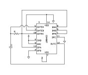
Yes the schematic is wrong, what's all the +1, +2 business about though?The schematic is off at the 4007. I think it should look like this: View attachment 108359
So (excuse the quick shoddy drawing) you want the attached.
Don't worry about testing it at +9V or +5V, looking at the SSI datasheet this morning, it doesn't have an internal divider akin to the Reticon chips as I assumed, just an inverter so it'll need a cleaner clock than the 4007 can provide... just find out the clock frequency the original gives and then a MN3102/CD4047 or the like can be shoved in its place.
Also while looking at the datasheet this morning I saw the specs on the SSI aren't as good as I'd hoped they might be for a new chip... it's going to be a bit of a balancing act between noise and distortion in this circuit.
Attachments
Bio77
Well-known member
It is a screen shot from a lecture I found, not sure about the 1s and 2s.Yes the schematic is wrong, what's all the +1, +2 business about though?
That's a bummer. In that case, would two 3009s be a better choice?Also while looking at the datasheet this morning I saw the specs on the SSI aren't as good as I'd hoped they might be for a new chip... it's going to be a bit of a balancing act between noise and distortion in this circuit.
With all the flangers you have designed, have you found the clock to have a minimal impact on the sound? I wouldn't have guessed that. For example, the Small Clone and Boss choruses sound so different, one has the CMOS clock and the other the 3102. Is it only about the frequency and sweep or does the quality/shape of the clock signal have an impact on the sound?Don't worry about testing it at +9V or +5V, looking at the SSI datasheet this morning, it doesn't have an internal divider akin to the Reticon chips as I assumed, just an inverter so it'll need a cleaner clock than the 4007 can provide... just find out the clock frequency the original gives and then a MN3102/CD4047 or the like can be shoved in its place.
Similar threads
- Replies
- 10
- Views
- 875
- Replies
- 0
- Views
- 163
- Replies
- 2
- Views
- 331