Pot Taper Sub Question

VanWhy

Well-known member
Is there some good info out there or some "rule of thumb" about subbing pots with different tapers? I guess I'm just trying to wrap my head around it.
I get the differences (I think) of a linear vs audio. Basically, linear goes in a straight line and audio goes on a curve. And then there is reverse audio taper which is self-explanatory. Mainly I'm asking when is it okay and when is it not okay to sub a reverse audio with an audio taper pot? I don't have a breadboard yet to test which is why I'm asking. I'm working on the Aberration Fuzz which calls for a C500K but I'm currently out. Is it all about how we perceive that sound increasing or are there other factors in the circuit at play?
 
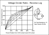
According GeoFex's "Secret Life of Pots", a B1M pot with a 1M resistor tied across lugs #1 & #3 will get you a good approximation of a C500K pot.
Thanks, that's a great resource. "Tapering Resistors". So, essentially this is wiring the pot to in parallel reducing the total ohms? That's where I see the 500K come in but don't understand how it changes the taper. Is that because of lugs 1 and 3? Sorry if these are dumb questions.
 
Changing tapers won’t affect a circuit’s functionality. It only changes how smoothly it goes from one extreme to the other with your ears. Changing a pots VALUE, either up or down, will affect the circuit or the stage before/after depending on what it’s doing
Thank you. Makes perfect sense.
 
... And then there is reverse audio taper which is self-explanatory. ...
Maybe not so self explanatory.
When I first started building, I thought a reverse audio taper meant the pot worked in reverse, which I loved the idea of so I could make mods that required me to install some boards backwards in enclosures (solder side out when looking into enclosure, so all the components are hidden). I was trying to get it to work without resorting to offboard wiring, I didn't realise the only way to achieve what I wanted was to reverse the wiring between pins 1 & 3 on the stock pot (whatever the taper). 😸


... Is it all about how we perceive that sound increasing or are there other factors in the circuit at play?

What Buddy said about functionality, whereas taper...
It's about perception, feel, preferences.
For example: Some people want unity at noon🕛, others at 9:00 🕘 and a few may even want it at 3:00 🕒. How that is achieved depends on where the knob sits in its rotation with the stock circuit, for example:

Some people prefer linear taper volume on any Muff (stock), others prefer to sub out the linear-volume for logarithmic.


Something that ramps up too quickly in the first part of the rotation, making it touchy and difficult to dial in, may benefit from a reverse taper. It depends on the function and what your preferred sweet-spot is.
 
You could also use an A500k pot but wired in reverse (swap 1 & 3) to get the same taper as C but the control will be backwards from the way it was intended. I do this all the time with rate controls on LFO's....
 
...a B1M pot with a 1M resistor tied across lugs #1 & #3 will get you a good approximation of a C500K pot.
That is absolutely wrong. It is not possible to make an A- or C-taper pot from a B-taper pot. The reason is that putting a resistor in parallel with a pot makes the high-resistance end of rotation change more slowly. With an A- or C-taper pot, it's the low-resistance end of rotation that changes more slowly.

Here's a simple calculation.

We'll start with a B1M pot, tie pins 1 & 2 together and connect a 1M resistor from pin 1 to 3. With the knob at 0 (7:00), the resistance from pin 1 to 3 is 500K. With the knob at 5 (noon) , the resistance from pin 1 to 3 is 333K (1M in parallel with 500K). The resistance of a C500K pot at noon is 75K. Not even close.
Hey, I was just repeating what I read in the article. I merely misquoted the lugs for which the external resistance is added. They should be #1 & #2 or #2 & #3. (Now corrected in my post.)

revlog.png
 
Last edited:
Back
Top