Power Supply Questions - Reverse Voltage Over Voltage

rossbalch

Active member
Hey folks. Given I design for myself and don't really have to worry about scale, I want to design things the "right way.

I'm designing pedal and studio gear. I think for some stuff I will use a linear power supply that will provide +12/0/-12 using a 5 pin din connector, so not worried about the wrong thing being connected.

For pedals though I will probably use an LT1054 for when I want +/-. I think I will use components in all designs that could withstand 15v (so at least 30v, probably minimum 63v caps for instance).

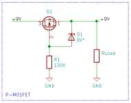
So here's my question, I think I want to use the MOSFET protection like this example. What properties am I looking for in a MOSFET (SMD is fine). I know P-channel. But what other datasheet points should I keep in mind? I saw someone recommend this https://www.lcsc.com/product-detail/C75561.html

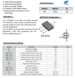
The VS voltage is 20v, is this too small for power supply spikes with a nominal voltage of 12v input? The Current - Continuous Drain(Id) is 2.8A. The RDS(on) is 74mOhms. I think I read that smaller is better (lower drop out voltage?).

Here's another candidate I thought might work https://www.lcsc.com/product-detail/C42457011.html

I'll be using the 1N4744A for over voltage protection which I think should protect the LT1054.

1756178274173.png
 
The other thing I have questions about is power filtering. Beyond the usual big/little combo for caps, are inductors and ferrite beads worth introducing into the filtering?
 
Drain source voltage rating higher than your power supply

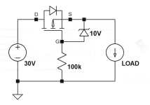
Vgss (max gate source voltage) above your power supply and use a zener to clamp gate source
1000007511.png
Lowest Idss-on rating you can find after narrowing the above.

Good video here
Specifics in the last couple minutes
 
If you've got voltage to spare (which you do), you can't beat a single Schottky diode for simplicity and minimal drop; 1N5819s cost nothing, drop minimal voltage and will withstand 40v continuous reversed all day.

IMO, reliant on a RC filter these days on the power rail isn't that useful for the majority of situations - it's very, very rare to see an unregulated or even linear power supply, so the majority of your noise is coming through outside of where this filter will be that useful. A ferrite bead and filter cap will do the job nicely, and won't drop much voltage either.

The biggest thing for noise for you is going to be your LT1054 layout; with that being said, you might be much better served using a DC-DC converter given your supply voltage, but will really depend on how much current you need. If it's under 100ma or so, you can make a fully isolated supply for next to nothing, with components needed to meet EMI noise spec only costing a few cents.

I'm open to a DC-DC converter, I guess my question is though, in audio situations, how much better is a regulated vs un-regulated one? The regulated versions seem to add about $10 to the price.
 
I'm open to a DC-DC converter, I guess my question is though, in audio situations, how much better is a regulated vs un-regulated one? The regulated versions seem to add about $10 to the price.
Honestly, it's not super important unless you're drawing a high proportion of the total device output - the difference in a few of the models I just compared was 1% voltage variation from 0-100% current draw for regulated vs 10% for unregulated (and the same from min to max input voltage). You shouldn't see massive swings in output current or input voltage so I wouldn't care too much.

More important is checking each devices stated ripple, switching frequency and minimum load - I've seen some with a minimum switching frequency of 20khz, some that don't guarantee better than 200mv ripple (can be filtered, but still 2.5x higher than others) and others that have a 10% minimum load.
 
How would you implement over voltage?
Check out this thread for some inspiration: https://forum.pedalpcb.com/threads/...cts-with-a-voltage-doubler-muzzle-klon.22033/

You can also go very simple and use a zener reverse biased to ground. It will shunt any voltage exceeding the zener voltage directly to ground. It's not very precise, can add noise and is likely to go poof in an actual overvoltage situation because it can't handle the current flowing through it. Adding an appropriately sized series resistor before the zener can help the protection circuit survive, but then you're dealing with a voltage drop across the resistor, which may or may not be acceptable.
I experimented with this yesterday night, and unleashed some magic smoke, but it was due to my breadboarding errors.

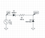
To me it looks like a 1N5817 schottky diode + 100Ω and a 10V zener diode (i used 1N4740 i think) would do a decent job att protecting the charge pump IC from from 18V input and -18V.

I had a nice curve too, but CircuitLab told me I had to pay before I had a chance to print it.

I don't know enough to know about what problems this can cause though.

Screenshot 2025-08-27 at 11.15.23.png
 
I experimented with this yesterday night, and unleashed some magic smoke, but it was due to my breadboarding errors.

To me it looks like a 1N5817 schottky diode + 100Ω and a 10V zener diode (i used 1N4740 i think) would do a decent job att protecting the charge pump IC from from 18V input and -18V.

I had a nice curve too, but CircuitLab told me I had to pay before I had a chance to print it.

I don't know enough to know about what problems this can cause though.

View attachment 101992
That will depend on the effect circuit. If it draws only 5 mA, then Ohm's law tells us there will be a 0.5V drop across the resistor. That's not too bad. If your circuit draws 50 mA, that resistor is now dropping 5V. No bueno.
 
Last edited:
Back
Top