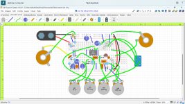
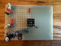
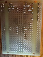
Well I learned something new about mosfets today don’t always assume pin layout on a schematic is the same as the mosfets orientation. I couldn’t get signal to my output jack. Turns out a J112 is DSG and a print always shows the arrow pointing at the gate so the print was showing DGS so I eventually figured out about pin orientation. So I got it working but when I crank it it’s farting out on me. I’m going to try a 15k resistor to see if I can tame the voltage down a bit it’s sitting at around 3.12V at the gate on the print it’s supposed to be 1.67V going to try a 15K resistor were the 10K is hooked up to the mosfet. Any ideas on this would really help.