Question - Distortion 250 Clipping Diode Options

cgreg714

Member
Hey all,
I'm going to build up my Distortion 250 board this afternoon, and I would like to have three clipping options:
-1N4148
-LEDs
-a yet-to-be-determined third option (possibly Schottky BAT41s?)

First time trying this, so my questions are as follow:
-is this even possible?
-is this possible with an on-off-on DPDT?
-am I correct in assuming that the LEDs would have to be put in place of both D1 and D2?
-would the DPDT center lugs be soldered to the anode of D1 and the cathode of D2?
-if three options are not a possibility, then would just the 1N4148s and the LEDs be a viable option with the DPDT?

Thanks for any and all advice.
If you want true LED clipping then yes, you'll need to put them in both D1 and D2. You can put any combination you'd like in there.

The lazier/cleaner solution to your mod is to socket those diode holes and try different diodes. I personally like a combo of red LED/1n4148. Just remember to have the diodes going opposite ways. You won't have the convenience to select them on the fly, but you'll have as many options as you want.

Now, if you want to have a diode selector that can get a little tricky depending on your building experience. No matter what, you're going to have to have a daughterboard with the switch/diodes separate from the pcb. If you want to go down the daughterboard route you'll need to solder some wire from the PCB to the daughterboard. One wire from the left side (signal) and the other wire coming from the right (ground).
1640809638826.png

For a 2 diode combo option, GuitarPCB sells some DPDT mod boards that I found incredible useful in my experimenting phases. For a buck it's totally worth it, but I would suggest either getting additional boards or something else from the site since the shipping alone is more than a buck. Here's the link https://guitarpcb.com/product/dpdt-wiring-board/. You can either socket everything on the board and experiment til the cows come home or solder the two sets of diodes on the board and call it a day. I personally would go with the former.

If you don't want to go down the daughterboard route you can simply solder the diodes directly to a dpdt switch. The wires would go to the center lugs.

If you want 3 diode clipping options you're going to need some stripboard. Do you have any? If you want to go down this road let us know and we can help you there rather than me writing another essay about it, LOL.
 
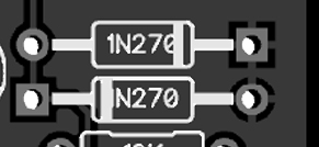
If you want true LED clipping then yes, you'll need to put them in both D1 and D2. You can put any combination you'd like in there.

The lazier/cleaner solution to your mod is to socket those diode holes and try different diodes. I personally like a combo of red LED/1n4148. Just remember to have the diodes going opposite ways. You won't have the convenience to select them on the fly, but you'll have as many options as you want.

Now, if you want to have a diode selector that can get a little tricky depending on your building experience. No matter what, you're going to have to have a daughterboard with the switch/diodes separate from the pcb. If you want to go down the daughterboard route you'll need to solder some wire from the PCB to the daughterboard. One wire from the left side (signal) and the other wire coming from the right (ground).
View attachment 20468

For a 2 diode combo option, GuitarPCB sells some DPDT mod boards that I found incredible useful in my experimenting phases. For a buck it's totally worth it, but I would suggest either getting additional boards or something else from the site since the shipping alone is more than a buck. Here's the link https://guitarpcb.com/product/dpdt-wiring-board/. You can either socket everything on the board and experiment til the cows come home or solder the two sets of diodes on the board and call it a day. I personally would go with the former.

If you don't want to go down the daughterboard route you can simply solder the diodes directly to a dpdt switch. The wires would go to the center lugs.

If you want 3 diode clipping options you're going to need some stripboard. Do you have any? If you want to go down this road let us know and we can help you there rather than me writing another essay about it, LOL.
-So I have a double side board from Tayda (SKU A-1191)...would that work?
-If I go the two option route with the DPDT switch, what pads am I soldering the two center lugs to? Left lug to left pad of D1 and right lug to right pad of D2?
 
Last edited:
-So I have a double side board from Tayda (SKU A-1191)...would that work?
Your tayda board will work. You will need a on-off-on spdt switch. I don't have a lot of experience with p2p type boards, but you'll need to make solder bridges either way. Here is a stripboard layout of a diode selection
1640870477373.png
The bottom strip will be ground. Once you have the diodes soldered in there you will need to make a solder bridge. Strip some hookup wire and solder it to every hole on that row. Attach this portion to the right side of the pcb diode section (see above post). You can tell it's ground because the holes have a + cut in them. The switch wiring is included here too. The blue wire in the diagram will go on the left side of the pcb diode (doesn't matter if you pick D1 or D2). The LEDs should be the center lug on the switch since they have the highest voltage drop.
-If I go the two option route with the DPDT switch, what pads am I soldering the two center lugs to? Left lug to left pad of D1 and right lug to right pad of D2?
As long as each pair of diodes is oriented correctly (opposite directions) it doesn't matter which center lug goes to where on the board. One lug to the signal chain (left side pcb) and ground (right side pcb).
 
in the past I would run the dpdt on off on with wires to the center lugs and LEDs across the center lugs ... the other diodes sets would be wired across the outside lugs of the switch ... so long as whatever you have mounted on the outside lugs has a lower Vf than the LEDs they will be what clamps the signal first when they are brought into parallel with the LEDs
 
  • Like
Reactions: mdc
FWIW I should also mention that if you want more gain on tap simply increase the value of R2. 1.5m or even 2m will work. The signal will start hitting the power rails of the IC (additional clipping).

To increase the bottom end of the sound increase C3. I would socket this one if you want to experiment.

Also, for this particular circuit a lot of people mention that the gain pot gets extremely sensitive toward the last 10% when you turn it clockwise, meaning there isn't much change in the sound until it's almost cranked fully. You can fix that by installing a C-taper 1M instead of the B-taper one. Just my 2 cents on this circuit...
 
Put 6 diodes on two DPDTs and then you can really party.

o2FnT4o.png
 
THis will be your best option IMO. Use on-off-on switches and make sure youve got the LED orientation right. Look at the other two diodes to see what i mean.
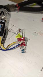
PXL_20211230_201053269.jpg
So I ended up doing this on the switch. 1N4148s on the top, BAT41s on the bottom. Left yellow wire went to the right pad of D2, right blue wire to the left pad of D1.

BUT....I also did this:
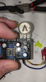
PXL_20211230_201100173.jpg
I soldered two red LEDs in D1 and D2 with the wires from the switch attached to the underside of the board. (Pardon the filthy board, picture was taken before I cleaned with 90% isopropyl)

-Will this work? My thought process is that while the switch is in the 'off' middle position it will use the LEDs for clipping, then in either 'on' position it will work for the respective diodes. If it won't, I'm going to desolder and go with MDCs two DPDT suggestion. Seems like fun.
 
I think with that arrangement you'll be good, the LED's will have the higher vf so when the switch is up or down current should flow through the other diodes with lower vf, I'm sure one of the resident Guru's will either verify or shame me soon
 
I think with that arrangement you'll be good, the LED's will have the higher vf so when the switch is up or down current should flow through the other diodes with lower vf, I'm sure one of the resident Guru's will either verify or shame me soon
That was what I was thinking as well. Did a little research and it seemed like this arrangement would make sense. Thanks for the feedback/info. This community is awesome because of people like you.👍
 
Back
Top