Relay Switching Advice

cyborgdiaspora

New member
I'm trying to figure out a way to make a switchable buffered splitter where two inputs can be routed to two outputs in all three possible combinations. This would be used with a guitar that has both mag and piezo outputs, with the idea that I can split the mag signal, split the piezo signal, or keep one of each. I am also hoping to control this device via a relay switching port on an MC6 Pro.

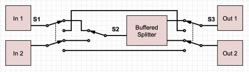
This diagram represents what I've come up with. The idea is that S1 and S3 would select between "bypass mode" or "splitter mode". Then S2 would determine whether "splitter mode" would split input 1 or input 2. S1 and S3 would be controlled by one remote switch while S2 would be controlled by the other.

Screenshot 2026-08-27 at 7.26.06 PM.png

I am planning to use this kit for a TL072-based buffered splitter and these pcbs for latching relays. I figured I should post my relay question here since this is where I'm getting the relay pcbs!

In order to get S1 and S3 controlled by the same remote switch, do I:

-Use one control circuit for both S1 and S3, then wire the coil pins from both relays in parallel? Or in series?
-Make a separate control circuit for S1 and S3, but have both control circuits wired to the same remote switch?
-Some other option?
 
Sorry if you read my first version of this reply - I had a major brain-fart. This is a re-write which is hopefully accurate!

Trying to follow your intent, the way your schematic is drawn now, I believe the truth table would be as follows. I am assuming that S1 and S3 always operate in tandem, so I am treating them as one switch.

S1+S3S2Out1Out2
UpUpBuffered In1Buffered In1
UpDownBuffered In2Buffered In2
DownUpNot-buffered In1Not-buffered In2
DownDownNot-buffered In1Not-buffered In2

There's technically four states, but with S1+S3 down, S2 is bypassed entirely, so two states are the same, resulting in three distinct states. Verbally, those three states are:
  • "Raw" or unbuffered in1 and in2
  • in1 only, but buffered and split across the two outputs
  • in2 only, but buffered and split across the two outputs

If my interpretation is correct: what you need are two double-pole, double-throw (DPDT) switches (S1+S3) and one single-pole, double-throw (SPDT) switch (S2).

I believe the combination of S1+S3 in tandem, i.e., two DPDT, would be a four-pole, double-throw (4PDT) switch.

A DPDT switch is basically two SPDT switches whose operations are synchronized in parallel. So you can use only "half" of a DPDT switch as a SPDT.

In order to get S1 and S3 controlled by the same remote switch, do I:

-Use one control circuit for both S1 and S3, then wire the coil pins from both relays in parallel? Or in series?
-Make a separate control circuit for S1 and S3, but have both control circuits wired to the same remote switch?
-Some other option?

Since S1 and S3 are always working in tandem, then they can be operated with a parallel control line. Even though they are two switches, I am thinking about them as one.

But you need two independent control lines for the two switches, S1+S3 and S2. With the parts you've specified, you would need two footswitches:
  • S1+S3: the PedalPCB Basic Relay Bypass (Latching) requires a momentary SPST footswitch - that sends a control signal to the PCB itself, which triggers the relay to do the actual signal (i.e. audio) switching; you'd need two of these (one for S1, one for S3), and could control them from a single momentary SPST switch
  • S2: the GGG IC Buffer requires a mechanical 3PDT switch for engage/bypass. Here the mechanical switch acts as both the "control line" and the actual signal-switching mechanism.

Personally, I would find this arrangement awkward, since S1+S3 in the "down" position means S2 does nothing when you push it. Also, momentary switches are typically smooth (no click) and the typical 3PDT switches do have a distinct click when pressed. That would annoy me.

Now you could of course use a third PPCB Relay Bypass for the Buffer as a replacement for the 3PDT switch. That's more consistent from a user-interface perspective (two of the same kinds of switches). But you still have two footswitches.

Re-reading your questions, I'm guessing that you only want a single footswitch. The problem is, a SPST momentary footswitch can only send two distinct signals: open or closed. You have three states but a single SPST switch can only describe two states. So you need two footswitches - or you need a more sophisticated logic circuit to drive the relays. I would reach for a microcontroller here, personally. It would easy to program the footswitch to cycle between the three states (i.e. each press advances to the next state). Or you could get fancy with double-taps and/or press-and-hold schemes.

I should also note that there's an argument that you should always buffer, otherwise the outputs will have wildly different output impedance, dependent on state. Again, depending on what follows the output, it might not matter... or it could be a big headache. Making all outputs buffered, regardless of state, means a consistent, predictable, low-output impedance.
 
Sorry if you read my first version of this reply - I had a major brain-fart. This is a re-write which is hopefully accurate!

Trying to follow your intent, the way your schematic is drawn now, I believe the truth table would be as follows. I am assuming that S1 and S3 always operate in tandem, so I am treating them as one switch.

S1+S3S2Out1Out2
UpUpBuffered In1Buffered In1
UpDownBuffered In2Buffered In2
DownUpNot-buffered In1Not-buffered In2
DownDownNot-buffered In1Not-buffered In2

There's technically four states, but with S1+S3 down, S2 is bypassed entirely, so two states are the same, resulting in three distinct states. Verbally, those three states are:
  • "Raw" or unbuffered in1 and in2
  • in1 only, but buffered and split across the two outputs
  • in2 only, but buffered and split across the two outputs

If my interpretation is correct: what you need are two double-pole, double-throw (DPDT) switches (S1+S3) and one single-pole, double-throw (SPDT) switch (S2).

I believe the combination of S1+S3 in tandem, i.e., two DPDT, would be a four-pole, double-throw (4PDT) switch.

A DPDT switch is basically two SPDT switches whose operations are synchronized in parallel. So you can use only "half" of a DPDT switch as a SPDT.


Since S1 and S3 are always working in tandem, then they can be operated with a parallel control line. Even though they are two switches, I am thinking about them as one.

But you need two independent control lines for the two switches, S1+S3 and S2. With the parts you've specified, you would need two footswitches:
  • S1+S3: the PedalPCB Basic Relay Bypass (Latching) requires a momentary SPST footswitch - that sends a control signal to the PCB itself, which triggers the relay to do the actual signal (i.e. audio) switching; you'd need two of these (one for S1, one for S3), and could control them from a single momentary SPST switch
  • S2: the GGG IC Buffer requires a mechanical 3PDT switch for engage/bypass. Here the mechanical switch acts as both the "control line" and the actual signal-switching mechanism.

Personally, I would find this arrangement awkward, since S1+S3 in the "down" position means S2 does nothing when you push it. Also, momentary switches are typically smooth (no click) and the typical 3PDT switches do have a distinct click when pressed. That would annoy me.

Now you could of course use a third PPCB Relay Bypass for the Buffer as a replacement for the 3PDT switch. That's more consistent from a user-interface perspective (two of the same kinds of switches). But you still have two footswitches.

Re-reading your questions, I'm guessing that you only want a single footswitch. The problem is, a SPST momentary footswitch can only send two distinct signals: open or closed. You have three states but a single SPST switch can only describe two states. So you need two footswitches - or you need a more sophisticated logic circuit to drive the relays. I would reach for a microcontroller here, personally. It would easy to program the footswitch to cycle between the three states (i.e. each press advances to the next state). Or you could get fancy with double-taps and/or press-and-hold schemes.

I should also note that there's an argument that you should always buffer, otherwise the outputs will have wildly different output impedance, dependent on state. Again, depending on what follows the output, it might not matter... or it could be a big headache. Making all outputs buffered, regardless of state, means a consistent, predictable, low-output impedance.
Thanks, this is so detailed!

To clarify my original plan, yes, the goal is to be able to cycle through three different states as you describe. Setting aside the MC6 pro to simplify it, let's say I have a remote switcher with two spst momentary footswitches, let's call them T and R. The scheme I've had was that T operates relays 1 and 3 to switch between bypass and splitter, then R operates relay 2 to determine which input will be split when the splitter is engaged.If I understand you correctly, this can be done with R activating one control circuit and T activating a second control circuit (albeit modified so that the control circuit activates two relays with the coils wired in parallel).

The idea that I should always buffer to help with impedance matching makes sense to me though, so maybe that's moot. One thing I've been uncertain about with splitter designs is if the buffer needs to go pre- or post-split. It seems like most examples I've seen split the signal first, then run each signal through a buffer. But of course that doubles the number of buffer circuits needed, so if it's possible to buffer then split that would be good, especially since two signals are being split.

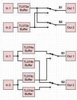
If I'm not trying to take the buffers out of the circuit, this also allows for a simpler switching scheme—I think.
 

Attachments

  • Screenshot 2026-08-28 at 2.12.11 PM.png
    Screenshot 2026-08-28 at 2.12.11 PM.png
    109.2 KB · Views: 3
To clarify my original plan, yes, the goal is to be able to cycle through three different states as you describe. Setting aside the MC6 pro to simplify it, let's say I have a remote switcher with two spst momentary footswitches, let's call them T and R. The scheme I've had was that T operates relays 1 and 3 to switch between bypass and splitter, then R operates relay 2 to determine which input will be split when the splitter is engaged.If I understand you correctly, this can be done with R activating one control circuit and T activating a second control circuit (albeit modified so that the control circuit activates two relays with the coils wired in parallel).

If indeed the T and R footswitches are SPST momentary (i.e. they are open- or closed-circuit normally, and then closed/opened only as long as the switch is actually pressed), then yes, that exactly matches what I laid out in my previous post.

As for buffer pre- or post-split. We're starting to get above my pay-grade, but... JFET- or CMOS-input opamps generally have extremely high input impedance, so you could likely get away with splitting before the buffer. (The TL07x is JFET input.) Consider your guitar pickups, typically modeled as having high(ish) output impedance: if you split it, and now have to drive two devices, you've literally doubled the load. But, an opamp like the TL07x presents so little load to the source that I feel like driving two in parallel is still an "easy" load.

That said, buffering post-split feels wrong. And it's definitely wrong if your buffer's input is low(ish) impedance. For example, you definitely wouldn't want to try to drive a pair of NE553x in parallel from guitar pickups.

So I would probably start by buffering both input signals before the switches or the splits. Most opamps have super-low output impedance. Splitting the signal doubles the output impedance (i.e. doubles the load). This might be OK. One downside, though, is you're back to having different output impedances depending on switching state. Although the difference wouldn't be nearly as dramatic compared to the buffered versus raw pickup signal case.

What I would do is four total buffers:
  • two as input buffers, for In1 and In2, before any switching
  • two as output buffers, for Out1 and Out2, after all the switching

You could also consider electronic analog switches instead of mechanical relays. For example, the CD4053 has three independent SPDT switches. So you'd need two of those. But they are cheap, current-production commodity parts, and being non-mechanical, should basically last forever. (Though to be fair, the modern mechanical relays like the Panasonic TQ2 series, when used for low-voltage audio switching, can be expected to last a lifetime.)
 
That makes sense! I may see how a two buffer setup works in both configurations and if neither sounds good I'll give four a try. Each output is going directly into a Tonex One with adjustable input trim, so that may help on the output side. Thanks again for all of your advice!
 
Back
Top