yazooligan
Well-known member
Congrats to the team on this! I wanted to make a modern pedal version of the X100 for years but abandoned it when I picked up a used X100 w/RockAdaptor for $150 a few years back.
still can't figure it out. I feeel real dumb. how do I strip the ".pdf" from the files?I'm sorry if this is a dumb question but how do I strip the .PDF from the files? I am stumped. I suck at computers. I tried renaming it but the .pdf doesnt appear there when I rename it.
They should end with ".ZIP" by changing the file name.(s) You may need to alter your PC settings to show the files extensions.I'm sorry if this is a dumb question but how do I strip the .PDF from the files? I am stumped. I suck at computers. I tried renaming it but the .pdf doesnt appear there when I rename it.
")
They should end with ".ZIP" by changing the file name.(s) You may need to alter your PC settings to show the files extensions.
It's really that simple.
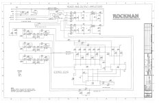
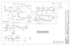
what about the comp mod? what does that replace on the original schematic?For those interested, here are the Rockman X100 Rev 10 schematics with modification & other notes.
View attachment 88981 View attachment 88982
The Comp mod replaces nothing. It's the simple addition of a pot in series between R14/R169 and the Test Point. Just above R14/R169, you'll see the B250K COM pot in the 1st schematic.what about the comp mod? what does that replace on the original schematic?
I'd have need to see the Rev 9 schematic to sort out what the hidden switch does.I recently rescued a X100 belt pack from a garage sale and after a bit of TLC on some damaged solder joints I have it up and running great! I'm wondering if you might be able to point me in the right direction for modding so that I can get a dry signal off the unit in addition to the Chorus/Echo/Both that it offers.
My circuit is a Rev. 9 which of course has some slight variations from the well-documented Rev. 10, one of which was a buried momentary switch (in-between the clamshell circuit boards and totally inaccessible without disassembly) in the input stage that I found gave it somewhat of a compressed boost that was very musical. I removed the switch and wired it to an SPST switch that I put on the side of the belt pack and have been using it with great success. Wondering if anyone has come across this detail and could shed some light on what might be going on there.

The Rockman X100 chorus circuit generally operates with a delay range of approximately 20–24ms or modulated around 17–23ms, designed to produce a wide stereo image.did you ever happen to get measurements for the range of delay that is modulated in the chorus circuit?