Sandspur Fuzz - Volume Loss

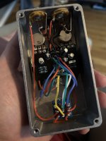
I’m working on a Sandspur Fuzz build and my bypassed signal works fine. The engaged circuit signal was working fine for about 5 minutes and then all on its own the volume dropped significantly. What are some common reasons this would happen?
 
I narrowed it down to a potentiometer. Is it possible I got some bad pots? I ordered these from Amazon. At first I thought it was my soldering, but I’ve soldered them three different ways and the result is always that they end up broken. I can get them to work if I put a little pressure on them, but they don’t work if I let go. Do I just need to order different parts or is there something I can try?

I break the little tab off, but am being as careful as I can while doing that. I wonder if the pressure needed to break the tab is causing the wiper inside to separate or something.
 

Attachments

  • IMG_0636.jpeg
    IMG_0636.jpeg
    730 KB · Views: 9
  • IMG_0635.jpeg
    IMG_0635.jpeg
    742 KB · Views: 9
I narrowed it down to a potentiometer. Is it possible I got some bad pots? I ordered these from Amazon. At first I thought it was my soldering, but I’ve soldered them three different ways and the result is always that they end up broken. I can get them to work if I put a little pressure on them, but they don’t work if I let go. Do I just need to order different parts or is there something I can try?

I break the little tab off, but am being as careful as I can while doing that. I wonder if the pressure needed to break the tab is causing the wiper inside to separate or something.

Use your multimeter and test them.
 
Use your multimeter and test them.
I’ve been doing that, and they work initially but by the time I solder, heat shrink, and install them, they break. I read through the reviews and was reading that they break easy. They can’t take much heat at all according to one review.

When I test a broken one, I get the OL reading until putting some slight pressure on the board, then I get numeric resistance readings. So, they are shorting out.
Interesting. Sounds like you should buy some better pots then!
 
Why? You have an internal “range” setting trimmer for the external bias control.


This.
What I’m trying to accomplish is bringing those internet controls to the outside. Explain to me why this is not a good idea. I know it has level, fuzz, and sundial on the outside. I’m assuming you are saying that the sundial is the bias where it’s min and max are controlled by the internal range trim pots. (Just trying to understand the circuit better.)
 

Attachments

  • IMG_9927.jpeg
    IMG_9927.jpeg
    300.6 KB · Views: 3
In the schematic you can see that both the bias trimpot and sundial pot influence the bias. It’s probably the most convenient to set the bias to 4,5v with the sundial pot in the middle so you can increase or decrease the voltage with the sundial.
 
What I’m trying to accomplish is bringing those internet controls to the outside. Explain to me why this is not a good idea. I know it has level, fuzz, and sundial on the outside. I’m assuming you are saying that the sundial is the bias where it’s min and max are controlled by the internal range trim pots. (Just trying to understand the circuit better.)

I see what you are after now.

Don’t bring the internal bias trimmer up top. That’s pointless. Set it so you get the widest range from the sundial. There absolutely no reason to have the internal bias trimmer up top.

As for the “Clean” trimmer, that is perhaps a million times more useful than external bias and I support that decision.
 
Back
Top Bottom