schematic to layout converter?

jaminjimlp

New member
What's out there that can do this? Without costing an arm and a leg?
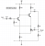
I found DIYLC (it's nice for drawing a clean schematic) and thought that it said it could do it but I put in a schematic and see no way to convert. I see perf board schematics like at dirtboxlayouts and I want to be able to "cleverly" convert my designs for my own stuff till I get something I might want to make PCB's for... if you are not shure what I am asking here is some pix. Thanks in advance.
 

Attachments

  • EHX Deluxe Big Muff EH3054C.png
    EHX Deluxe Big Muff EH3054C.png
    341.3 KB · Views: 17
  • EKI 826.png
    EKI 826.png
    33.5 KB · Views: 17
VeroRoute, DIYLC. Or any other PCB design software (Kicad, Eagle and so on..) - you can set the grid to 2.54mm and design your own "vero".
But still - you draw the schematic and then place the components in the right place, manually.

So you're saying that DIYLC can do it as well once I draw the schematic? Or do I have to draw the schematic with the components that they show in the component section and then I can move it around or is that program not able to really do it that way I do like the feature of being able to take the schematic and move the parts around and it makes the lines go where they need to keep some connected so that the circuit is still right I think that's going to be key in getting the best layout. Reason I ask about that one is I've already downloaded it and put a schematic into it but couldn't ever find a way do the layout
 
I rarely use DIYLC, but I don't remember it being based on a schematic. I'm sure you can use DIYLC to draw one, but that's all probably.
With DIYLC you simply look at the schematic, select the appropriate components from the library and arrange them like a puzzle to fit together properly. And you can't be sure you haven't missed anything. There are PCB design programs that are based on schematics. They show which components are connected to each other, which is very helpful and minimizes the risk of error. But these are not programs dedicated to vero.
 
Last edited:
DIYLC lets your draw layouts, but it doesn't automatically convert a schematic to a layout. You have to draw the layout yourself. Once you get used to vero board and it's horizontal traces it's pretty easy to make a layout for something simple like your fuzz box.
 
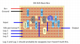
I was bored before bed and made a quick layout. It could probably be cleaned up and compacted a little bit, but I spent ten minutes throwing it
together. Try following each of the lines on the schematic and following them on this layout:

View attachment 64140
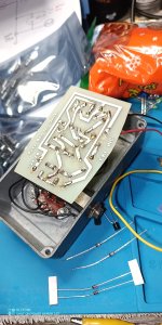
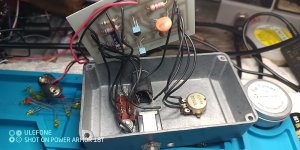
LOL I have an EKI 726 right here I got from a kit I bought back in the early 90's the only difference is the pot is 100k instead of a 50k.
 

Attachments

  • IMG_20231226_232050_069.jpg
    IMG_20231226_232050_069.jpg
    367.5 KB · Views: 8
I first got into making pedals through various sites showing Vero layouts. At that time I thought how on earth do they convert a schematic into a Vero layout?

Then I started to make little changes to suit how I prefer to build. For example I much prefer to have film box caps span over 3 rows and no more, because that's how they are designed to fit. If unavoidable I will put a film cap over 2 rows because it's easy to hide the bend under the cap.

Once I had started doing this I found I could do my own layouts. Now I rather like drawing up layouts. It's a kind of puzzle to get everything just how you like it. A lot of the layouts available online don't work with the parts I like to use, or have the wiring all over the place. They might not leave enough space for a 100µF cap. And sometimes you just have to wonder what they were on when they drew them!
 
Hamish, one of the little things on the vero layouts that always drove me nuts was when they would use a 1uf electrolytic cap and bend the legs so it spanned more than two neighboring holes that they should sit in. I'd rather run a jumper and make a cut if I have to just to avoid that. I'll even run jumpers across the board just to have all three wires for a potentiometer come out at the same place. The board is more cluttered, but the offboard wiring is a little less of a nightmare. The worst was when one wire came off the left side of the board and the other two came off the right. It was like a spiderweb.
 
Back
Top