
gtfields13
Well-known member
- Build Rating
- 5.00 star(s)
The campaign to put PCBs to cases is underway. Not much Phido Sound branded as these were my test builds for all the different PCBs I bought last summer, which I built over the winter.
First up is a Seabed Delay - a PT2399 basic delay with only three controls. I wanted to get this one cased because I am sure I am going to want to run a stereo pair of these when I'm performing my experimental music. EDIT. Speaking of which, I put my second copy into a case. I tried out a combined IO board for this build, along with some other variations in the wiring, cutting down on the connectors a little bit.


Maybe the only noteworthy point is that I have built a pair of these. One with the PT2399 from PedalPCB, and one with a Lingxing IC copy that I bought from LCSC electronics. No, I really can't hear a difference. When I build to sell, I will probably stick with PTC chips because I am not trying to be lowest cost, anyways. There is definitely a bit of ticking I can hear if I turn the gain way up, but for my practical purposes (i.e. live performance) it's perfectly fine. If I really wanted perfection, I'd stay in the DAW and process delays digitally.
I would like to figure out where to tap so that I could run a second LED in time with the rate. I didn't spend more than a moment reading the PTC data sheet, but that didn't show an obvious answer (like when there is an LFO on a Phaser).
My unified IO board was successful, and I definitely prefer this, although it was more expensive to Fab. In this case, I've configured for many options - i.e on board (square style) power, separate through hole power (connected view leads). Battery connector pads with either an offboard battery switch or using the audio-ring to enable battery.

Until the next case event. AKA tomorrow, since I already have dropped the Byzantium Flanger into it's case.
First up is a Seabed Delay - a PT2399 basic delay with only three controls. I wanted to get this one cased because I am sure I am going to want to run a stereo pair of these when I'm performing my experimental music. EDIT. Speaking of which, I put my second copy into a case. I tried out a combined IO board for this build, along with some other variations in the wiring, cutting down on the connectors a little bit.


Build
The build was straightforward. Nothing complicated really, and I built it to spec. I don't know that I would want to do much more with this particular design. It fits the bill for simple, minimal controls that are all directly useful.Maybe the only noteworthy point is that I have built a pair of these. One with the PT2399 from PedalPCB, and one with a Lingxing IC copy that I bought from LCSC electronics. No, I really can't hear a difference. When I build to sell, I will probably stick with PTC chips because I am not trying to be lowest cost, anyways. There is definitely a bit of ticking I can hear if I turn the gain way up, but for my practical purposes (i.e. live performance) it's perfectly fine. If I really wanted perfection, I'd stay in the DAW and process delays digitally.
I would like to figure out where to tap so that I could run a second LED in time with the rate. I didn't spend more than a moment reading the PTC data sheet, but that didn't show an obvious answer (like when there is an LFO on a Phaser).
EDIT Build - 2
The second build uses the Lingxing 2399 IC. No problems on the auditorium. But did you know that if you wire both the power leads and the LED leads in reverse, the LED will light up appropriately, as if nothing is wrong. The board will not, however, function. And (in fact) it is possible that this will have a deleterious effect on the PT2399. Good thing the Lingxing chips are cheap (0.29).My unified IO board was successful, and I definitely prefer this, although it was more expensive to Fab. In this case, I've configured for many options - i.e on board (square style) power, separate through hole power (connected view leads). Battery connector pads with either an offboard battery switch or using the audio-ring to enable battery.
Finish
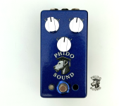
I put this in one of my batch of generic cases from Tayda. If your curious, this is Candy Metallic Blue. It looks better in person than I was able to photograph. Enough metal flakes to keep my inner hot rodder happy. I'll come back to this when the brand goes on. EDIT: For the second build I tried out some green aluminum knobs that I bought for a different project where they are too large. I think I like this look for my delay pedals.
The Sound
Definitely going to have some demo fun with stereo delays...Until the next case event. AKA tomorrow, since I already have dropped the Byzantium Flanger into it's case.
Attachments
Last edited:
