Simple Level Meter

benny_profane

Well-known member
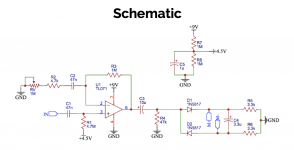
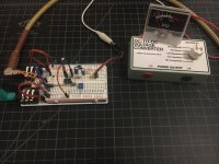
First project is up on Protoboard Micro. I took inspiration from @fig and attached the board via velcro to swap out projects without tearing down. Here, I'm working on a simple level meter based on a project offered by MAS Effects. The first stage is a buffer that allows for a bit of level correction and frequency filtering. Then, the signal is rectified so it can be fed to a meter. I'm still working on tuning this. I know I'm not going to be able to get a true VU meter from this setup (the needle isn't the most accurate, either), but open to suggestions. I'm thinking I want to limit bass either with the coupling cap or in the buffer stage. The release is pretty quick right now, so I may increase the cap after the rectifier.

DC Meter Driver Schematic.png

breadboard vu (small).JPG
 
I did not. You've been buying up their entire stock! I picked these up off of ebay. I'm still not entirely sure what I want to do with this. I've already designed an LED meter using the audiometer chip from Electric Druid. I just really like making lights flash and needles bounce I think.

EDIT: There's some interesting discussion here.
 
Last edited:
  • Like
Reactions: fig
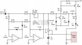
I was interested in trying out the peak level indicator, so I put the following circuit together. The meter performs very well and the trimmers are very useful. I'm having trouble getting the peak LED to work, though. I set it up as a split rail, however I lowered the supplies to +/-9V. I'm also using 2n5088 and 2n5087 devices instead of BC550 and BC560. Should anything else in the transistor network be modified?


1040peak570.png
 
Last edited:
A couple of points from the article....
Did you reduce the CLR for operating at 9VDC?
Also need 100nF across the TL072 power pins.

Please let me know how you get it working (so I can build it too!)
 
I used regular power filtering practices and have the cap across the TL072 power pins. I installed a trimmer for the CLR. Rebuilt this twice and still no peak indication. I’m thinking something else needs to be adjust for the lowered power source, but I’m at a bit of a wall. Does the 330k resistor from Q2 collector to Q1 base need to be adjusted?
 
  • Like
Reactions: fig
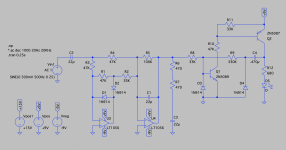
I wanted to verify the circuit with a +/-9V supply and work with different values in LTSpice. The peak LED indicator doesn't work unless the signal is amplified enough with U2 (U4 in the Spice schematic below). The following schematic has the negative feedback resistor set to 100k and the CLR lowered to 680R.

SPICE DC Meter with Peak Indicator.png

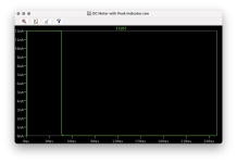
The following plot shows the current through the indicator LED.

DC Meter LED Current Plot.png

Given sufficient settings for the U2 gain trim (i.e., 'sensitivity' in the linked schematic) and an appropriate CLR value, the circuit should work fine with guitar signals at +/-9V without further modification.
 
  • Like
Reactions: fig
Back
Top