yazooligan
Active member
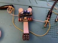
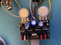
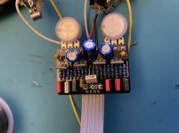
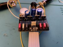
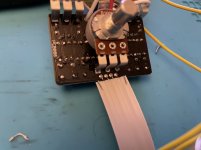
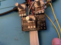
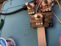
Sound comes through in bypass, but no sound when the footswitch is engaged.
I haven’t soldered an LED in yet; does it need one to complete the circuit?
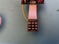
Also my first time using the PPCB smd J201’s, and I used legs from 100uf capacitors for leads. They fit snug in the sockets.
I haven’t soldered an LED in yet; does it need one to complete the circuit?
Also my first time using the PPCB smd J201’s, and I used legs from 100uf capacitors for leads. They fit snug in the sockets.
Attachments
-
 EFFDA983-D851-4976-82DE-4807549B1918.jpeg315.1 KB · Views: 19
 -
 7BB1992A-D969-4823-930A-8EF3E692BD51.jpeg204.4 KB · Views: 20
 -
 9FE5792A-FACA-4407-86D1-8630199E6B46.jpeg201.4 KB · Views: 18
 -
 4B3DC744-2112-4F12-837C-F7F811C4806B.jpeg233.8 KB · Views: 17
 -
 56A47B78-3A39-4292-8CB2-01D5F5B86AEF.jpeg182.5 KB · Views: 17
 -
 A8EC18CB-3F09-4844-98FD-2D54BF8390FD.jpeg324.3 KB · Views: 17
 -
 CD51C0C5-F10B-4EDD-A76D-7946ADDBCE4C.jpeg234.4 KB · Views: 17
 -
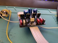 C7893C49-6767-4DB2-BA65-BA81C3E7B222.jpeg206.6 KB · Views: 18
 -
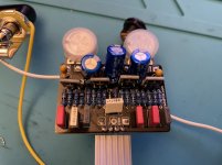 8590E550-85B1-4C11-BD80-19F870C734EB.jpeg218 KB · Views: 18
 -
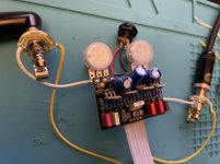 70A17D60-7713-4FFD-A286-57B6A3978A9E.jpeg209.9 KB · Views: 19


