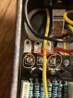
If you look at the gain pot in the schematic, it creates a 1M resistance to ground through lugs 1 and 3 (plus the 22K from R8). What you are doing when you add another resistor across lugs 1 and 3 is decreasing the resistance to ground by putting additional path for the signal to go through. Whatever signal that does not go to ground is increased in the feedback loop when you increase the resistance with the gain pot, but only the part of the signal that is not already going to ground.
It is worth trying this approach because it is easy although it will also change the taper on the pot a bit. Could be a change that gives you even more fine adjustment over the last part of the rotation.
If you were interested in seeing how the taper might change you could also put a 1M resistor between lugs 1 and 2, and maybe also 2 and 3. This kind of trial and error ideal for breadboarding, but not too hard when you are just adding resistors between lugs on a pot.
 . Is it by any chance possible to make subtle gain reduction in “Stoner” mode on the Softii pedal? I love it to bits but I feel like the gain on the stoner mode quickly gets out of hand. I rarely use it past noon and mostly at 8-9’ish so I would love to take it back a notch. Kindly remember I’m a noob but I can swap a resistor or two if that could make a difference.
