djmiyta
Well-known member
Pedal is stuffed, pots and jacks wired up, everything but the bypass switch
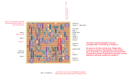
I did this layout
https://dirtboxlayouts.blogspot.com...ite.html?sc=1753678096700#c841080721134874214
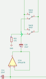
from this schematic
On the layout there are 2 places connecting to lug 3 of the dpdt foot switch. I believe this to be a typo but I can't prove it .
Could anyone please take a look at the schematic ( which shows a 3pdt by pass switch ) and tell me what lug numbers of the bypass switch go where. I tried a couple of times but started pulling my hair out and I been bald for 35 years.
Also, I don't see anywhere lug one goes to . looks like it's connected to something on the schematic
I don't think this would be any problem figuring out from the other smarter 99% of this pedal building community. (Sorry you 1%'s we're all in the same boat paddling around with one oar in a circle and I don't wanna be the captain but I just might be.)
I did try using my test box but got nothing ( no signal) I kinda thought I should get a signal at the output even if I didn't wire the foot switch in but it being part of the circuit I guess not. ANY clarification would be so very appreciated so thank you in advance


