ttf
New member
Hi wonderful folks, I am having a hard time troubleshooting a Kliche Mini I am building. The gain pot is misbehaving and I could not understand why.
To give a background, I am experimenting on some mods I read on the Coda Effects site, specifically:

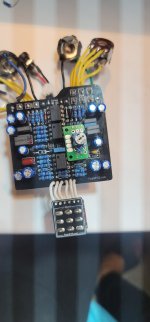
During my testing, the clipping diodes worked (switch between Ge and LED), the more gain mod worked (replace 2k with a lower value or jumper), but I was having issues with the fat switch. I found that the posts I installed in the C7 holes were faulty, and so I tried replacing and I might have ruined one of the C7 pads:
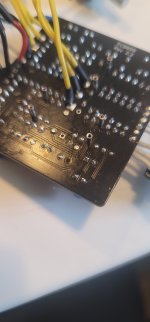
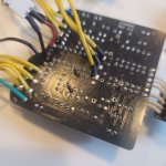
Now I read the schematic and I see C7 is in parallel with R10 15k, so it means I should be able to put both C7 (along with its mod, which is simply an SPDT that adds another cap in parallel), AND R10 as well. So I took R10 out, replaced with sockets and ran some wires to go to a breadboard, where R10 and C7 are in parallel. This is how it looks like (this is just a photo to show how the mod looks like, the mods for the diodes and gain are not connected in the photo).
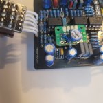
So of course I hooked it up with all mods connected, and now the gain knob is behaving in a strange way. From 0 to maybe 30% there is only a faint sound. At around 30 to 35% (very narrow sweep) there is some clean sound, which seem to be affected by the treble pot. Past that, I am getting a very dark and faint signal, up until 100%.
Things I've done so far:

Hopefully someone can chime in and throw some ideas as I am all out of them lol I might think I've checked everything but as I am a novice I'm not sure I'm being objective so I would like to ask for help. Thanks in advance!
To give a background, I am experimenting on some mods I read on the Coda Effects site, specifically:
- More gain (decrease Kliche R9 value)
- Fat switch (increase value of C7)
- Diode switch

During my testing, the clipping diodes worked (switch between Ge and LED), the more gain mod worked (replace 2k with a lower value or jumper), but I was having issues with the fat switch. I found that the posts I installed in the C7 holes were faulty, and so I tried replacing and I might have ruined one of the C7 pads:

Now I read the schematic and I see C7 is in parallel with R10 15k, so it means I should be able to put both C7 (along with its mod, which is simply an SPDT that adds another cap in parallel), AND R10 as well. So I took R10 out, replaced with sockets and ran some wires to go to a breadboard, where R10 and C7 are in parallel. This is how it looks like (this is just a photo to show how the mod looks like, the mods for the diodes and gain are not connected in the photo).

So of course I hooked it up with all mods connected, and now the gain knob is behaving in a strange way. From 0 to maybe 30% there is only a faint sound. At around 30 to 35% (very narrow sweep) there is some clean sound, which seem to be affected by the treble pot. Past that, I am getting a very dark and faint signal, up until 100%.
Things I've done so far:
- Replaced dual B100K with a fresh one
- Reflowed all joints, especially the ones close to the mods I made and most especially the socket posts
- Removed mods (i.e. took out switches and simply wired the stock values in the breadboard)
- Checked continuity between the components close to the ones with mods and the gain pot, all good.
- In the process of reflowing and resoldering, I might have exposed some capacitors to excess heat, specifically the electrolytics and ceramic surrounding C7. Before I try to replace these components I wanted to see if this may be causing the issue
- Possibly something in the C7 holes? My understanding is that C7 connects to the same nodes as R10 in parallel so I can connect C7 where R10 goes.


Hopefully someone can chime in and throw some ideas as I am all out of them lol
I might think I've checked everything but as I am a novice I'm not sure I'm being objective so I would like to ask for help. Thanks in advance!