Stumble boost - Stumbling around to learn about frequency cutoff/gain/etc.

like Yeah!

Member
edit- see post #6 for the results of this learning experience. Once again, thank you to everyone that has answered my questions across the forum in the past few weeks!

ok, so i've built a stumble and decided i don't completely like the eq voicing, but i do like the idea of it being essentially an effects loop in a pedal.
it is too warm, not enough treble definition for me.
the low cutoff seems fine, it's just too warm overall in the upper frequencies.

i want to learn how to swap parts the right way instead of guessing and throwing parts around.. i don't know where to start in this circuit for doing any of this, but i've read enough to know i have to calculate the resistor/capacitor values i'd be changing with a formula to get where i want to go.. so i figured i'd start with a basic circuit like this, and ask. i found some calculators at a site called muzique but i don't know how to make use of that properly so now i'm confused..

what parts of that circuit would i want to look at to get a higher/crisper treble cutoff frequency? i'm not sure if i'm stating this properly.. but i'm trying to stay away from le buzzwords as much as i can ha

schematic is here. https://docs.pedalpcb.com/project/Stumble-PedalPCB.pdf

thank you
 
Last edited:
I'm not familiar with this one. Have you tried each part of the circuit separately? From the Input to the Send, and then Receive to the Output. Do they both sound warm, or just one side?
 
I'm not familiar with this one. Have you tried each part of the circuit separately? From the Input to the Send, and then Receive to the Output. Do they both sound warm, or just one side?
good question, so i went and tested that... both sides sound equally 'rounded'..

for more context, while i was testing it again i noticed that it's a subtle difference if you are only playing into it clean.
when you put dirt into it though, it is very noticable.
so for example, it sounds okay out on a pedalboard, but if you stick it in an amp fx loop (or after distortion)... it actually sounds poop because the high frequencies are all shelved off in this weird rounded 'i'mma, a warm circuit' way.
 
Last edited:
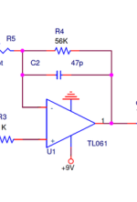
Ok, both sections are similar to an MXR MicroAmp but with different value components and the gain is not variable.

This is a good place to start to understand what the circuit is doing. You don't have to do all the math.
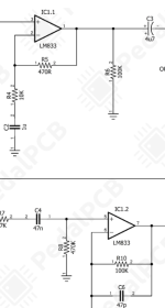
i guess the side with the capacitor (c6 on the stumble) is the side that is controlling the low pass?
both circuits use the same value for the capacitor that doc says is part of the low pass, but use different resistances..
on the microamp that's c2 and the resistor next to it , r4, is 56k..
the resistor next to c6 like that in the stumble is r10, and that's 100k

so that's the reason the stumble sounds duller than the micro amp when it's pushed?


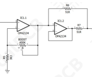
edit- i just looked at the schematic for the transcendence boost again, because i just built one and love how that sounds... it does not appear to have a low pass filter capacitor at all in the feedback loops. does that mean i can simply just remove c6 in the stumble to get the same effect? pic related.

edit 2- i found this low pass calculator that does the calculation.. https://www.learningaboutelectronics.com/Articles/Low-pass-filter-calculator.php
the original value for c6 of 47pf gives it a low pass value of 33.8khz if i leave the resistor at r10 alone (100k). if i want around the same low pass as a micro amp (60.469khz).. according to that calculator, the capacitor at c6 should be 27pf, which will give me a low pass of 58.976khz?

so i can either remove c6 completely, and have no hf feedback fitlering at all like a transcendance, or replace c6 with a 27pf and get roughly the same low pass as a micro amp?

edit 3- So i just took c6 completely out of the circuit and the hf roundness is gone. not noticing any problems and I don't have any 27pf caps around, so i'm just going to playtest it like this until i do another component order.. Thanks for the tips!
 

Attachments

  • Screenshot 2026-10-08 at 02-38-40 Transcendence Boost - Transcendence-PedalPCB.pdf.png
    Screenshot 2026-10-08 at 02-38-40 Transcendence Boost - Transcendence-PedalPCB.pdf.png
    31.3 KB · Views: 6
  • Screenshot 2026-10-08 at 02-42-06 Stumble Boost - Stumble-PedalPCB.pdf.png
    Screenshot 2026-10-08 at 02-42-06 Stumble Boost - Stumble-PedalPCB.pdf.png
    67.2 KB · Views: 6
  • Screenshot 2026-10-08 at 02-42-18 MXR MicroAmp Analysis · ElectroSmash Archive.png
    Screenshot 2026-10-08 at 02-42-18 MXR MicroAmp Analysis · ElectroSmash Archive.png
    17.3 KB · Views: 6
Last edited:
Here's a final update of sorts to the flogging of a stumble circuit to learn some things.

- So i just took c6 completely out of the circuit and the hf roundness is gone
After playing the circuit with c6 removed, and then again after installing a 27pf cap.. i decided that it didn't sound like it improved anything beyond removing c6 completely did, so then i wondered how hard it would be to give the boost section some more final output volume.. and maybe make it variable gain while i was in there throwing parts around to see how it effected the circuit.

apparently it's not that hard.

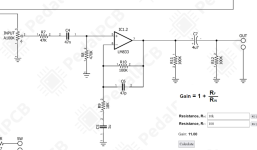
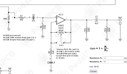
the circuit as built by the docs provides a final fixed gain of 11. I wanted to see what it was like with a variable gain of 16 (same as a transcendence boost). i was also curious to see if switching it to variable gain would reduce the noise floor at all. having the opamp be fixed gain means that the noise floor is always at 11, no matter what. ...along with your input attenuated signal, whatever that is..

So i started to hack around.

-Remove the A100k pot, R10, R9, and C6.

I didn't want to disturb what the first opamp section was handing to the final section, so i replaced the a100k pot with something that looks like a 100k pot turned all the way up.

-install a 100k resistor from pad 1 to pad 3 where the A100k pot was
-install a jumper from pad 3 to pad 2 where the A100k pot was

The vacant component holes from R10 and C6 will be used to accommodate the variable gain pot. i used a calculator to get the new values for the A50k pot and 3.3k resistor needed to get a gain of around 16.

-install an A50k pot where r10 used to be
-legs 1 and 3 use the r10 holes. leg 3 goes to the R10 hole closest to the output pin.
-leg 2 goes to the C6 hole closest to the output pin..
-install a 3.3k resistor in R9

Overall, removing the low pass cap and switching to variable gain in the last opamp stage (+ more gain overall) feels like an improvement to the pedal.. removing the low pass cap didn't have any negative effects in my ear tests, and it sounds better when you throw gain into it now.. it seems less noisy at rest too, because the noise floor is tracking with the output gain knob instead of being at 11 all the time with the attenuated input like it does as initially built.

it was fun. it's given me some ideas for a combination pedal build.
 

Attachments

  • Stumble-before-variable-gain-mod.png
    Stumble-before-variable-gain-mod.png
    122 KB · Views: 5
  • Stumble-after-variable-gain-mod.png
    Stumble-after-variable-gain-mod.png
    135.6 KB · Views: 5
Last edited:
Back
Top