Switching order dual overdrive (AionFX Gladiator/King Tone Duellist)

Matopotato

Active member
In the Aion FX Gladiator build the two sides or channels are in fixed order. (TubeScreamer type in to BluesBreaker type) Still they are separate so that there is an input and output for each of the sides. There is also Send and Return but that seems to live its own integrated life.
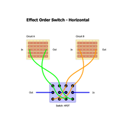
Looking at a few threads: 3PDT Order Switch Wiring and 2 in 1 pedal order switch there seems to be solutions with either 3PDT or 4PDT on/on toggles to switch order.
1. Where would the ins and outs for such a switch go?
1774717396145.png

2. Would there be any point in doing this or is the opposite order (BB into TS) from the designed one not really useful?

3. Would there be any issues with the Loop if an order switch is introduced or is it quite symmetrical/transparent?
 
I double posted this question on another forum as well. And since then I have come up with a possible solution, so here it is:

I think I have figured out as much as that the wires in the wiring schematic from AionFX doc would need to "desolder" the wire+pad labelled: Jack In, Snd, Ret and Jack Out.

Then in the 3 stomp layout:

2in1toggle.jpg

one can sort of ignore the top two ones and assume that the daughterboard connects the Jack In and the 3PDT for A (sort of Ch A In, but only when engaged), 3PDT for A with Snd pad (again when engaged), so the way to reach 3PDT A is in from Jack In and back out on Snd.
Similar the Ret is the way to 3PDT B and comes back on Jack Out pad.

Then the bottom stomp in the 3 layout would have the Input jack connected as labelled.
The green wire to Jack In pad, and the cerise goes to Snd.
The orange to Ret and olive green to Jack Out.
And the blue Out to the output jack.

That leaves the cables for the Loop. I thought that the criss-crossing wires in the bottom 3PDT could be "cut" and the loop inserted, And for the purple one this would be ok. (B to Loop to A)
But for the reverse I end up with wanting the cerise and orange connection to be "cut" and loop inserted. But in that case the "wire" to cut is inside the switch so that would not work.
So either the whole wiring needs rethinking, or it is not possible with a 3PDT.

But in this thread, post #4 shows a 4PDT solution.


Here the Loop would need to go between the A and B which is at the blue center horizontal wire.
Nicely enough, the direction is the same regardless of the 4PDT setting, so Loop wire would go to the right lug and return wire from the left lug of the two. And cut the blue line.
 
Back
Top