The week on the Breadboard: The FuzzDuster - cb style

Chuck D. Bones

Circuit Wizard
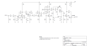
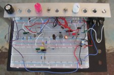
You may recall a contest I ran last year where I challenged the group to build a non-BMP circuit on a BMP board. Jason conjured up the FuzzDuster, an all-JFET BMP. Naturally, I had to breadboard it and then tweak it a bit. Fast-forward 18 months and I'm thinking about the FuzzDuster again. One of my first fuzzes was a borrowed BMP. The BMP was never one of my favorites, but I find myself drawn back to it. What can I do to make a BMP sound the way I want? Not so dense. Less noise. So I breadboarded the Fuzzduster once again and started making tweaks. With some input from Jason, here's where I ended up. Not nearly as much gain as a BMP, but enough for my purposes. The MODE switch add about 8dB more gain and fattens up the bottom-end a bit. Q2 runs without clipping diodes for a more open sound with less compression. Jason used JFETs wired as diodes for clipping. I use BA482s, which have a nearly identical V-I curve. The MID switch selects between a treble-cut tone control like in the BD-2 and a traditional BMP-style tone control. Back when I built my Ungula (EQD Hoof), I noticed that the clipping stages can be biased hotter (higher current) for a bit more gain without the transistors saturating. That's because the clipping diodes limit how far the collector (or drain in this case) voltage can swing. There are a lot of subtle differences in how the circuit operates when converting from BJTs to JFETs. The biasing is obviously different. There are no feedback resistors and the input impedance of each stage is very high. I dialed-in the bias on each stage by selecting JFETs and tweaking the source resistors. Many other JFETs will work, including J201 & 2N5246. You want something with a low Vp and Idss. All component values are negotiable. This circuit was optimized for Humbucker pickups, but works equally well with single-coils. If you want a fatter bottom-end, increase C3. Unlike the BMP, resistors R7, R12 and R16 do not affect the gain. They are there to prevent RF oscillation. The source resistors can be bypassed for a little more gain and tone-shaping. Q4's gain is set just below the clipping threshold, so I would not recommend increasing the gain of that stage.
FuzzDuster - cb mod v3.1.png

FuzzDuster v3.1 breadboard 02.jpg
 
Last edited:
I used some MMBFJ201s, there was a little playing around with the bias to get things right but it came right in the end.
I have a bunch of other JFETs I could trial but they're all in SMD and I don't know if I have enough adapter boards.

Not overly keen on the BMP tone stack, but that's a personal preference, I respect the Muff but I never find one which stays on the board for too long. Still debating whether to do a layout for this one, if I do then I will put in trim pots for bias and change R13/19, but I may give the Celestial Overdrive a whirl before looking at this one.
 
For a long time I was not a fan of the BMP tone stack either. Once I got rid of the mid scoop, I found ways to get tones I like. Did you try the treble-cut config (S3 in the UP position)? You can also try removing R3 and reducing C4. Or try the Page-1 FATNESS control. It's a variation on the BMP.
 
The treble-cut config rocks, I much prefer that. The gain switch is almost redundant, there's so much on tap :D

I should get back into BMP exploration, I have a Muffin Factory and there are a couple of settings on there which really gel with me. Mainly low gain up-front, I think HamishR mentioned that was one of his favourite configurations.
 
This thing is low-gain by BMP standards. I measured the max gain from input to Q3-C. 47dB with TURBO off, 60dB with TURBO on. A typical BMP peaks out at 70dB or so. I don't count the gain in the last stage because all of the distortion and compression happens in the 1st three stages.
 
The treble-cut config rocks, I much prefer that. The gain switch is almost redundant, there's so much on tap :D

I should get back into BMP exploration, I have a Muffin Factory and there are a couple of settings on there which really gel with me. Mainly low gain up-front, I think HamishR mentioned that was one of his favourite configurations.
You could try replacing the gain switch with a C5K pot for a bass/girth control.
 
The girth control works nicely. I think that’s a better option because you can dial it in. (And pots are cheaper than switches these days!?!).

I also swapped the BA482 for BA282 because I have a tone of them and not too many 482s. They’re pretty close in Vf and it seemed to tighten it up just a little. Any recommendations on other options? I’ll do a layout for this, but would rather avoid hard to find stuff if possible. I’ll try some different diodes soon, but want to make it as user friendly as possible.
 
Yes and no. It does very little. You need a much larger source resistor (Rt1) for the above method to have any range. If you increase the source resistor, then you need a JFET with a larger Vp. The biggest problem with the above method it is varies the gain at all frequencies, so it's not much of a bass control.

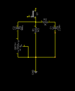
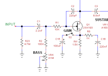
Here's a better way to make a variable bass-cut. The bass cutoff freq varies from 66Hz to 723Hz. If you want a different range, tweak C1. Note that I moved R1.

[edit] If you want it to get mo' fatter when BASS is dimed, then increase C3. Try 22nF, 47nF or even 100nF.

1691341866301.png

you can keep or ditch the GAIN switch.

BTW, I'm about ready to rip up this breadboard so I can proceed with the next project. Any further analysis on my part will be via LTSpice simulations.
 
Last edited:
Marvellous, thanks a lot. I'll sleep on this overnight and see if it's a hell yeah or a pass on the layout.
 
Back
Top