Chuck D. Bones
Circuit Wizard
I was combing thru my schematic collection and ran across this circuit. A quick listen to an Andy Martin demo and it was time to breadboard! The EHX version is built around an NTK275 PNP Germanium transistor. Apparently, EHX wanted to keep the number of different part values to a minimum. The ferrite beads and 100pF caps are there to reduce RF interference. EHX puts them in many of their pedals.

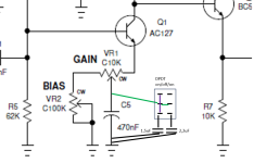
I have some AC127s (NPN Ge) that I wanted to audition, so I flipped the polarities and ended up with this. Q1 is the amplifier stage. Not all that different from a RangeMaster. Q2 acts like a variable power source. With the VOLTS control, you can dial from 3V to almost 9V for powering Q1. Q3 is a buffer to keep whatever comes next in the pedal chain from loading Q1. The BIAS control varies Q1's collector current from around 40μA to almost 300μA. The GAIN control varies the gain from just above unity to about 35dB at 1KHz with all knobs dimed. All of the knobs interact and there are a whole lotta tones in there from clean to treble boost to light OD to gated fuzz. At low gain, the freq response is flat. At high gain the bass and mids are rolled-off and we have a treble booster. Reduce C1 to cut the bass at lower GAIN settings. Increase C5 if you want more bass at higher GAIN settings. Or install switches. The BIAS pot makes it possible to use just about any Ge transistor in this circuit. The AC127 I have in there is quite leaky (Icbo = 450μA) and it works great.

To me, it seems pretty weird to build a dirt pedal with no volume control, but it works ok here.
Knobs, L-R: VOLTS - BIAS - GAIN.
Q1 in the center. Q2 is just below the VOLTS pot. Q3 is lurking beneath Q1. On the far left are an MP38A and a 2N1308 on deck.