
Chuck D. Bones
Circuit Wizard
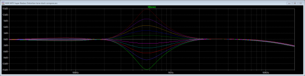
Here's the Kanengomibako trace:

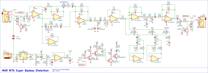
Lotta stuff in there. U5A is the input buffer. The next two stages (U1A, U1B, D3 & D5) resemble the Marshall Guv'nor. C3, C11, C12, R16 & R17 provide a treble bleed that only has an effect when DISTORTION is at zero. More on that circuit later. After the LED clippers we have another buffer, followed by a gyrator 3-band EQ. R13, R18-R20, C9 & C16 provide some low-pass filtering. U3C buffers the output and provides signal inversion for the cork-sniffers. There's some JFETs and BJTs for muting the input and output and driving the on/off LED. The SPX3819M5 is a low-dropout regulator.
It sounds pretty good right outta the box, but there are a lotta opportunities for simplification and improvement.
First, let's get rid of the extraneous parts. We can ditch the input and output muting (Q6-Q10 and associated Rs & Cs). In the treble bleed circuit, C11 & R3 do all of the work. We can jumper C3 & C12 and remove R16 & R17. I made the treble bleed a little stronger by reducing R3 to 3.3K and increasing C11 to 4.7nF.
C15 is unnecessary since there is only a few mV of DC across C15 and the last stage has unity gain. Jumper C15. I also left out the regulator (U6) and Vref buffer (U5B) Between U5B and unused opamp U2A, I saved a dual opamp. To stiffen Vref, I reduced R66 & R67 to 4.7K and increased C42 to 47uF.
There is a headroom problem. If we dime all of the knobs, U3C & U3D will saturate. I moved the VOLUME (OUTPUT) pot ahead of the tone stack by replacing R7 & R15 with an A250K pot (pin 3 to C6, pin 2 to U2-5 and pin 1 to Vref). VR2 is replaced by a 100K anti-pop resistor.
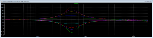
Finally, I retuned the tone stack and fiddled impedances so that I could use B-taper pots. VR4-VR6 are now B10K. R9 & R21 are increased to 22K. C17 is now 1nF (I might reduce it to 470pF). I adjusted the impedances and retuned all three filters. Here are the new values:
C22 = 150nF
C23 = 27nF
C25 = 5.6nF
C26 = 12nF
C27 = 4.7nF
R28 = 3.6K
R29 = 3.9K
R230 = 4.7K
R31 & R32 = 180K
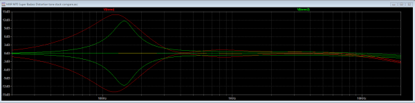
BASS peaks at 125Hz.
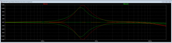
MID peaks at 550Hz.
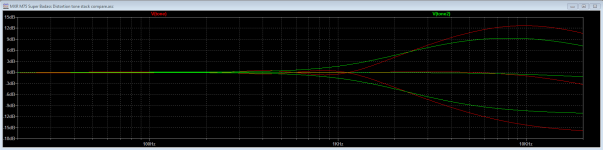
TREBLE takes effect above 1.5KHz.
I rearranged the opamp pairing. The first 2 stages are now U1. The next two stages are U2. The tone amplifier and output stage are U3. The gyrators are U4. U3 & U4 could be combined into a quad, like they are in the original circuit. I used two duals on the breadboard for ease of assembly.
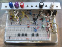
The opamps are arranged with U4 on the far left, then U3, U2 & U1 to the right. I put in a Vref trim to see if that did any good. so far, keeping Vref centered seems best. I've tried swapping a few different opamps such as LM833, TL072, NE5532 and TLC2272. Right now, it's all TL072s and it sounds good.
Knobs (L-R): BASS - MID - TREBLE - VOLUME - DISTORTION

Lotta stuff in there. U5A is the input buffer. The next two stages (U1A, U1B, D3 & D5) resemble the Marshall Guv'nor. C3, C11, C12, R16 & R17 provide a treble bleed that only has an effect when DISTORTION is at zero. More on that circuit later. After the LED clippers we have another buffer, followed by a gyrator 3-band EQ. R13, R18-R20, C9 & C16 provide some low-pass filtering. U3C buffers the output and provides signal inversion for the cork-sniffers. There's some JFETs and BJTs for muting the input and output and driving the on/off LED. The SPX3819M5 is a low-dropout regulator.
It sounds pretty good right outta the box, but there are a lotta opportunities for simplification and improvement.
First, let's get rid of the extraneous parts. We can ditch the input and output muting (Q6-Q10 and associated Rs & Cs). In the treble bleed circuit, C11 & R3 do all of the work. We can jumper C3 & C12 and remove R16 & R17. I made the treble bleed a little stronger by reducing R3 to 3.3K and increasing C11 to 4.7nF.
C15 is unnecessary since there is only a few mV of DC across C15 and the last stage has unity gain. Jumper C15. I also left out the regulator (U6) and Vref buffer (U5B) Between U5B and unused opamp U2A, I saved a dual opamp. To stiffen Vref, I reduced R66 & R67 to 4.7K and increased C42 to 47uF.
There is a headroom problem. If we dime all of the knobs, U3C & U3D will saturate. I moved the VOLUME (OUTPUT) pot ahead of the tone stack by replacing R7 & R15 with an A250K pot (pin 3 to C6, pin 2 to U2-5 and pin 1 to Vref). VR2 is replaced by a 100K anti-pop resistor.
Finally, I retuned the tone stack and fiddled impedances so that I could use B-taper pots. VR4-VR6 are now B10K. R9 & R21 are increased to 22K. C17 is now 1nF (I might reduce it to 470pF). I adjusted the impedances and retuned all three filters. Here are the new values:
C22 = 150nF
C23 = 27nF
C25 = 5.6nF
C26 = 12nF
C27 = 4.7nF
R28 = 3.6K
R29 = 3.9K
R230 = 4.7K
R31 & R32 = 180K
BASS peaks at 125Hz.
MID peaks at 550Hz.
TREBLE takes effect above 1.5KHz.
I rearranged the opamp pairing. The first 2 stages are now U1. The next two stages are U2. The tone amplifier and output stage are U3. The gyrators are U4. U3 & U4 could be combined into a quad, like they are in the original circuit. I used two duals on the breadboard for ease of assembly.
The opamps are arranged with U4 on the far left, then U3, U2 & U1 to the right. I put in a Vref trim to see if that did any good. so far, keeping Vref centered seems best. I've tried swapping a few different opamps such as LM833, TL072, NE5532 and TLC2272. Right now, it's all TL072s and it sounds good.
Knobs (L-R): BASS - MID - TREBLE - VOLUME - DISTORTION
Last edited: