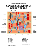
This Week on the Breadboard: The Yankee ScrewDriver Deluxe Turbo

If you have a breadboard, you can build just enough of the 1st stage to check the bias.
Hi again (and sorry again).

I had to raise R18 from 33k to 470k to get to a drain voltage of 5.5v on Q1. Does this seem outlandish? And is there a downside to ending up with this much higher value?

The other thing I'm struggling with is getting Q5-E up to your suggested 5.3v starting point. The highest I can get there with the trimmer is 4.1v.
 
Last edited:
Hi again (and sorry again).

I had to raise R18 from 33k to 470k to get to a drain voltage of 5.5v on Q1. Does this seem outlandish? And is there a downside to ending up with this much higher value?
No, 470K is fine. Even removing R18 is fine. No downside.

The other thing I'm struggling with is getting Q5-E up to your suggested 5.3v starting point. The highest I can get there with the trimmer is 4.1v.
This is not a troubleshooting thread, but let's see if we can solve this quickly. Did you sub any parts?
Measure these four voltages:
Q4-D, Q4-S, Q3-C, Q3-B
 
No, 470K is fine. Even removing R18 is fine. No downside.


This is not a troubleshooting thread, but let's see if we can solve this quickly. Did you sub any parts?
Measure these four voltages:
Q4-D, Q4-S, Q3-C, Q3-B
Thank you for your forbearance.

I built it exactly to the stripboard layout attached (with the exception of the germanium transistor and the aforementioned resistor change).

Q4 (BS170). D =8.94v, S - 4.8v
Q3 (104NU71). C = 3.4v, B = 0.65v
 

Attachments

  • PedalPCB Yankee Screwdriver Deluxe.png
    PedalPCB Yankee Screwdriver Deluxe.png
    190.8 KB · Views: 7
OK, I see what's going on. When you find Vero layouts on the internet, you use them at your own risk. I found one error on this board in about 30 sec. There may be others. I'll let you compare that layout to my schematic. If the error I found is the only one, then fixing your board will be easy.
 
Back
Top