Chuck D. Bones
Circuit Wizard
The TS, HM-2 and some other pedals use a type of active tone control that had been in common use in graphic equalizers for quite some time. In its most general form, the tone circuit looks like this:

R1 & R2 are usually equal, but they don't have to be. VR1 is often a W-taper pot, although with careful component selection it can be linear taper. Z is a generalized impedance. In a TS, it's a resistor and capacitor in series. In the HM-2, it's a gyrator (or two gyrators in parallel). In some graphic equalizers, it's a series R-L-C. This 5-band graphic equalizer was published in the October 1970 issue of Popular Electronics.

Q1 is an input buffer. Q2-Q4 form a rudimentary opamp. So you can see, this active filter design has been around for a long, long time.
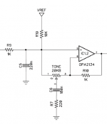
The TS is the simplest, so we'll tackle that one first. The schematic below is from the LGSM. It's the same as the generalized circuit above, with the addition of R19 (which does next to nothing) and C5, which adds some extra hi-cut. Z is replaced by C6 and R7. The opamp's feedback loop attempts to keep the + and - inputs at the same voltage. When the TONE pot is at zero (wiper all the way to the left), C6 and R7 are in parallel with C5. R9, C5, R7 and C6 form a low-pass filter with a corner freq at 400Hz. No current flows thru the TONE pot because both ends of the pot are at the same voltage. The opamp acts like a unity-gain buffer. Now suppose the TONE pot is at max (wiper all the way to the right). There is still no current flowing thru the TONE pot, but now C6 and R7 are inside the feedback loop (along with R10). At very low frequencies, C6 acts like an open circuit and the gain is unity. At very high frequencies, C6 acts like a jumper and the gain is 1 + R10 / R7 = 5.55 = 14.9dB. The transition from 0dB to 14.9dB happens over the range from 725Hz to 4KHz. But C5 and R9 are always there making a passive low-pass filter at 720Hz. When the TONE pot is centered, the circuit is balanced and there is no boost or cut (except the cut caused by C5).

The freq response looks like this. Each line represents the TONE pot going from 0 to 1, 2, 3, and so on up to 10.

Notice how most of the lines are bunched together. If we change the TONE pot to W-taper, the lines spread out. Pretty obvious why most TS clones use a W-taper pot.

Now let's look at the HM-2 tone controls. There's a LOW control and a HIGH control. It's the same basic circuit as the generalized circuit at the top of this article, except there are two controls and the Z elements are made from gyrators. So what's a gyrator? It's a circuit that transforms one impedance into another. In this case, it turns a capacitor into an inductor. There are lots of ways to make gyrators; this is the simplest way. Some gyrator circuits use an emitter follower instead of a unity gain opamp. The Blues Driver is an example of that.

Without getting into the gory details, the circuit made up of R21, R25, C13 and IC2.2 simulates an inductor. The inductance is equal to L = R21 * R25 * C13. In this circuit, L = 2.24H. It's not a perfect inductor, it has a series resistance equal to R25 and a parallel resistance equal to R21. The gyrator and C16 form the Z element in the generalized circuit, with inductance L in series with R25 and C16. It's equivalent to one section of the 5-band equalizer at the top of this article. When we put an R, L & C in series, we get a network that has a resonant frequency Fr = 1 / (2*pi*sqrt(L*C)). In this case, the resonant frequency is 87Hz, which can make a peak or notch in the frequency response, centered at 87Hz. Here's what it looks like in simulation. The LOW pot is swept and the HIGH pot is at noon.

IC3 and the surrounding components form a pair of series-resonant networks connected to the HIGH control. The two networks are stagger-tuned (960Hz & 1.3KHz) to provide a wide peak in the treble range. Here's the High control sweep with LOW at noon.

Clearly, the HM-2 would benefit from W-taper pots. Alternatively, the pots could be lower resistance (B1K). All of the HM-2's gyrators are easily retuned to change the center freq and Q.
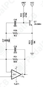
One more gyrator example: Blues Driver BD-2. The BD-2 uses a gyrator in the feedback loop of the last stage to create a bass hump around 120Hz. That gyrator is realized using an emitter follower. It works exactly the same as an opamp-based gyrator.


The mod makes the pedal's overall freq response extend deeper into the bass region. The mod consists of increasing C17 to 330nF, decreasing C18 to 6.8nF and increasing R20 to 4.7K.
The gyrators we have been studying in this article all have one end of the simulated inductor at AC ground. That works out fine because where gyrators are used in pedals, that's what we want. It's possible to make a gyrator where both ends of the simulated inductor are floating, but it takes two opamps. In all of the pedal circuits where gyrators are used, the simulated inductor is part of a series-resonant R-L-C network. The resistor on the output side of the opamp (R25 in the HM-2) is the R in the R-L-C network and its value is chosen accordingly. That resistor determines the network's impedance at the resonant frequency. That R and the L/C ratio (C is C16) determine the Q. There is interaction between the Rs and Cs, but with two resistors and two caps to play with, we have enough degrees of freedom to tune the network any way we like.
There's no free lunch and gyrators have their downside: they can be noisy. Referring to the top gyrator in the HM-2 circuit, The R25/R21 ratio is the "noise gain" of the circuit. That means the opamp's inherent input noise is multiplied by the noise gain. In this case 100K / 330Ω = 303 = 50dB. That's pretty much the practical limit for pedal circuits. The Q of the inductor is determined by the resistor ratio. I tried to make a high Q inductor for a CryBaby using a gyrator and it was very noisy because the noise gain ended up over 60dB. This explains why nobody uses gyrators in wah-wah pedals.
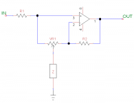
R1 & R2 are usually equal, but they don't have to be. VR1 is often a W-taper pot, although with careful component selection it can be linear taper. Z is a generalized impedance. In a TS, it's a resistor and capacitor in series. In the HM-2, it's a gyrator (or two gyrators in parallel). In some graphic equalizers, it's a series R-L-C. This 5-band graphic equalizer was published in the October 1970 issue of Popular Electronics.
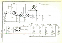
Q1 is an input buffer. Q2-Q4 form a rudimentary opamp. So you can see, this active filter design has been around for a long, long time.
The TS is the simplest, so we'll tackle that one first. The schematic below is from the LGSM. It's the same as the generalized circuit above, with the addition of R19 (which does next to nothing) and C5, which adds some extra hi-cut. Z is replaced by C6 and R7. The opamp's feedback loop attempts to keep the + and - inputs at the same voltage. When the TONE pot is at zero (wiper all the way to the left), C6 and R7 are in parallel with C5. R9, C5, R7 and C6 form a low-pass filter with a corner freq at 400Hz. No current flows thru the TONE pot because both ends of the pot are at the same voltage. The opamp acts like a unity-gain buffer. Now suppose the TONE pot is at max (wiper all the way to the right). There is still no current flowing thru the TONE pot, but now C6 and R7 are inside the feedback loop (along with R10). At very low frequencies, C6 acts like an open circuit and the gain is unity. At very high frequencies, C6 acts like a jumper and the gain is 1 + R10 / R7 = 5.55 = 14.9dB. The transition from 0dB to 14.9dB happens over the range from 725Hz to 4KHz. But C5 and R9 are always there making a passive low-pass filter at 720Hz. When the TONE pot is centered, the circuit is balanced and there is no boost or cut (except the cut caused by C5).
The freq response looks like this. Each line represents the TONE pot going from 0 to 1, 2, 3, and so on up to 10.

Notice how most of the lines are bunched together. If we change the TONE pot to W-taper, the lines spread out. Pretty obvious why most TS clones use a W-taper pot.

Now let's look at the HM-2 tone controls. There's a LOW control and a HIGH control. It's the same basic circuit as the generalized circuit at the top of this article, except there are two controls and the Z elements are made from gyrators. So what's a gyrator? It's a circuit that transforms one impedance into another. In this case, it turns a capacitor into an inductor. There are lots of ways to make gyrators; this is the simplest way. Some gyrator circuits use an emitter follower instead of a unity gain opamp. The Blues Driver is an example of that.
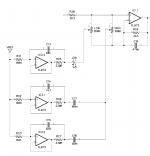
Without getting into the gory details, the circuit made up of R21, R25, C13 and IC2.2 simulates an inductor. The inductance is equal to L = R21 * R25 * C13. In this circuit, L = 2.24H. It's not a perfect inductor, it has a series resistance equal to R25 and a parallel resistance equal to R21. The gyrator and C16 form the Z element in the generalized circuit, with inductance L in series with R25 and C16. It's equivalent to one section of the 5-band equalizer at the top of this article. When we put an R, L & C in series, we get a network that has a resonant frequency Fr = 1 / (2*pi*sqrt(L*C)). In this case, the resonant frequency is 87Hz, which can make a peak or notch in the frequency response, centered at 87Hz. Here's what it looks like in simulation. The LOW pot is swept and the HIGH pot is at noon.

IC3 and the surrounding components form a pair of series-resonant networks connected to the HIGH control. The two networks are stagger-tuned (960Hz & 1.3KHz) to provide a wide peak in the treble range. Here's the High control sweep with LOW at noon.

Clearly, the HM-2 would benefit from W-taper pots. Alternatively, the pots could be lower resistance (B1K). All of the HM-2's gyrators are easily retuned to change the center freq and Q.
One more gyrator example: Blues Driver BD-2. The BD-2 uses a gyrator in the feedback loop of the last stage to create a bass hump around 120Hz. That gyrator is realized using an emitter follower. It works exactly the same as an opamp-based gyrator.
The freq response of the last stage looks like this. Green trace: stock response; indigo trace: modified response.
The mod makes the pedal's overall freq response extend deeper into the bass region. The mod consists of increasing C17 to 330nF, decreasing C18 to 6.8nF and increasing R20 to 4.7K.
The gyrators we have been studying in this article all have one end of the simulated inductor at AC ground. That works out fine because where gyrators are used in pedals, that's what we want. It's possible to make a gyrator where both ends of the simulated inductor are floating, but it takes two opamps. In all of the pedal circuits where gyrators are used, the simulated inductor is part of a series-resonant R-L-C network. The resistor on the output side of the opamp (R25 in the HM-2) is the R in the R-L-C network and its value is chosen accordingly. That resistor determines the network's impedance at the resonant frequency. That R and the L/C ratio (C is C16) determine the Q. There is interaction between the Rs and Cs, but with two resistors and two caps to play with, we have enough degrees of freedom to tune the network any way we like.
There's no free lunch and gyrators have their downside: they can be noisy. Referring to the top gyrator in the HM-2 circuit, The R25/R21 ratio is the "noise gain" of the circuit. That means the opamp's inherent input noise is multiplied by the noise gain. In this case 100K / 330Ω = 303 = 50dB. That's pretty much the practical limit for pedal circuits. The Q of the inductor is determined by the resistor ratio. I tried to make a high Q inductor for a CryBaby using a gyrator and it was very noisy because the noise gain ended up over 60dB. This explains why nobody uses gyrators in wah-wah pedals.
Last edited:


