
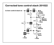
Hey all, I’m trying to get my head around tone stacks and their related components. In the schematic bellow, there are 2 x 470n caps. Now, I know that increasing the one that feeds into the bass pot will increase the bass content, but what about the one that goes to VB ? What would increasing/decreasing it do and how does it inter play with the other 470n?

You are using an out of date browser. It may not display this or other websites correctly.
You should upgrade or use an alternative browser.
You should upgrade or use an alternative browser.
Tone Stacks
- Thread starter ac30irons
- Start date

JohnnyCreepy
Well-known member
But there is no schematic. 
Just checking people’s observations !!!But there is no schematic.

Passinwind
Well-known member
The second one affects how wide the bass boost curve is, specifically by changing the low midrange scoop frequency. I can post a sim later, I would need to change the nominal Hiwatt component values as you have.Hey all, I’m trying to get my head around tone stacks and their related components. In the schematic bellow, there are 2 x 470n caps. Now, I know that increasing the one that feeds into the bass pot will increase the bass content, but what about the one that goes to VB ? What would increasing/decreasing it do and how does it inter play with the other 470n?

falco_femoralis
Well-known member
Passinwind
Well-known member
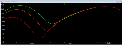
Here are some sims from my tube Hiwatt model:
Bass = .75, Mid = .8, Treb = .33 (out of 1.0), 47n cap to ground stock, then changed to 27n and 100n:

Same settings, second 47n cap also cycled between 27n, 47n. and 100n:

Bass = .75, Mid = .8, Treb = .33 (out of 1.0), 47n cap to ground stock, then changed to 27n and 100n:
Same settings, second 47n cap also cycled between 27n, 47n. and 100n:
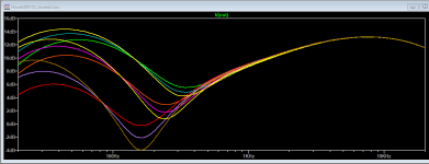
So if you have started at 47n - these are both 470nHere are some sims from my tube Hiwatt model:
Bass = .75, Mid = .8, Treb = .33 (out of 1.0), 47n cap to ground stock, then changed to 27n and 100n:
View attachment 125965
Same settings, second 47n cap also cycled between 27n, 47n. and 100n:
View attachment 125966

Passinwind
Well-known member
I used the values for a DR103 tube amp. if you have scaled them correctly to your source and load impedances the curves would be very close once scaled (i.e. 270n/470n/1uF). My particular model would be a bit of a PITA to port to a solid state format, so I’d need to at least know if you are using opamps, FETs, BJTs, etc. Do you have a whole schematic worked up yet?So if you have started at 47n - these are both 470n
Edit: this morning I got to work on my take on a viable solid state scaling using opamps. I'm now reasonably close but still need to see your basic concept to take it further. But here's where things stand right now, using your component values, same control settings as my perevious graphs, and both caps cycled through 270n, 470n, 1uF:
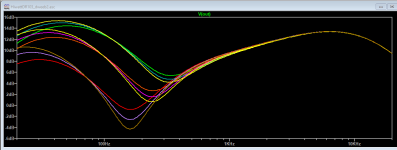
Pretty danged close!
 I had to do some tweaks around the opamps to get there, but just very simple stuff affecting high and low frequency rolloff shapes.
Last edited:
Dude - this is too too cleaver and quickly reminds me that I’m guessing at this stuff.I used the values for a DR103 tube amp. if you have scaled them correctly to your source and load impedances the curves would be very close once scaled (i.e. 270n/470n/1uF). My particular model would be a bit of a PITA to port to a solid state format, so I’d need to at least know if you are using opamps, FETs, BJTs, etc. Do you have a whole schematic worked up yet?
Edit: this morning I got to work on my take on a viable solid state scaling using opamps. I'm now reasonably close but still need to see your basic concept to take it further. But here's where things stand right now, using your component values, same control settings as my perevious graphs, and both caps cycled through 270n, 470n, 1uF:
View attachment 126032
Pretty danged close!
I’m very much a try it and see type. I have used a dumble type schematic (the Bajaman one that I already build.) Iv swapped out the tone stack and toggles for the stack posted. The bass pot was acting as an on/off - Iv swapped that out for a A100k and swapped the non grounded 470nf for a 1uf.
It sounds bloody great. Clean as a whistle, bags of head room. Iv also put a Violet Rams Head on the board and that smashes the shit out of it.
If you want a board, dm me your address, I no doubt there are some efficiencies that could be made.