BourbonAndGames
New member
Everything turns on, but not able to tune or get signal out. I can toggle the buffer modes and hear the relay clicking when switching from 1 to 2 or 1 to 3 and reverse, but no clicking from 2 to 3. Unsure if that is normal.
IC1 Pin 8 reads 8.58vdc to ground.
IC2 Pin 8 reads 5vdc to ground
IC3 and IC4 Pin 8 reads 8.67vdc to ground.
X1-5V pad reads 5vdc to ground.
The Green LED for charge flashes at the same interval, maybe a second in between each one?
Factory Reset and uploaded Firmware from the website as a just in case.
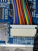
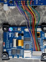
Did the build after awhile of not doing any plus using a new iron and without a good PCB holder. Eventually got it settled down mostly. I've checked component values and diode placement, but that doesn't mean I didn't miss it. I may de-solder the wires to the interface and re-do them as I'm not exactly happy with them but as far as I can tell they aren't an issue.
Thank ya!
Edit: I also used two different 9v power supplies, both rated 400mA+.


IC1 Pin 8 reads 8.58vdc to ground.
IC2 Pin 8 reads 5vdc to ground
IC3 and IC4 Pin 8 reads 8.67vdc to ground.
X1-5V pad reads 5vdc to ground.
The Green LED for charge flashes at the same interval, maybe a second in between each one?
Factory Reset and uploaded Firmware from the website as a just in case.
Did the build after awhile of not doing any plus using a new iron and without a good PCB holder. Eventually got it settled down mostly. I've checked component values and diode placement, but that doesn't mean I didn't miss it. I may de-solder the wires to the interface and re-do them as I'm not exactly happy with them but as far as I can tell they aren't an issue.
Thank ya!
Edit: I also used two different 9v power supplies, both rated 400mA+.