Nightendday86
New member
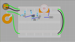
It's a little abstract for me to understand, but am I doing this right? I'm following this schematic, http://www.bigmuffpage.com/images/KR_1973_V2_No 3 Schematic.jpg


I'm literally just trying to make it fit, and this is the first I've ever done one, Thank you for the corrections!Q2 diodes aren’t connected fully
Correction. Both sets of diodes need to go from collector to base. You may need to rearrange your layout
Also the recovery stage is a bit of a mess. Is it possibly to clean it up a bit?

Once you get to a nice layout on breadboard, it's fairly straightforward to mount it on Veroboard for a more permanent arrangement. Just beware of the 'off-by-one' mistakes that I made, hence why some resistor legs are squew in the example.It's looking great for a first try. I've only done a few myself, you'll get better at organizing the layout each time.
Don't be discouraged if it doesn't work right away and you need to walk through it again.
I like to think of it in terms of the nodes, and how many "things" should be attached to each node.
For example, all the red dots below are the same node (same exact place in the circuit) and all green things are hooked to the same node.
Likewise, the Q2 base also has 6 things connected to it. Since you can only fit 5 on a breadboard line, you'll need to link a couple of rows to allow enough connections:
View attachment 24310

