Tuner not tuning

red

New member
HI, i've tried to built the Q.tune,

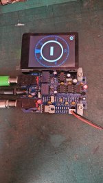
it doesn't tune, the tuning screeen stay in - posizion, if i press the footswitch it mutes and lets the signal pass,

i've measured the voltage and i have those:

1. 9V on Pin 8 of each NE555 (IC3 & IC4). i have 8,78v
2. 5V on Pin 8 of MCP6002 (IC2) i have 1,v
3. 9V on Pin 8 of TL072 (IC1) i have 7,59v
4. 5V on the X1-5V pad (which powers the ESP32) i have 5,01

since they are wrong, i checked the components but haven't seen mistakes
i've tried to update it but no difference.

Could you help me?
 

Attachments

  • DSC08358.JPG
    DSC08358.JPG
    626.4 KB · Views: 9
  • DSC08357.JPG
    DSC08357.JPG
    751.3 KB · Views: 8
  • DSC08356.JPG
    DSC08356.JPG
    633.1 KB · Views: 8
  • WhatsApp Image 2025-09-02 at 15.04.07 (1).jpeg
    WhatsApp Image 2025-09-02 at 15.04.07 (1).jpeg
    384 KB · Views: 7
  • WhatsApp Image 2025-09-02 at 15.04.07.jpeg
    WhatsApp Image 2025-09-02 at 15.04.07.jpeg
    358.7 KB · Views: 9
Sorry you’re experiencing any problems. First off, your build looks nice and clean and I don’t spot anything obvious. Just to double-check, the green cable you have plugged into the output jack. Is that correct? One other thing to try is going into Settings (tap the Q logo at the bottom right of the screen) > Tuner > Bypass Mode. Do you hear the relay click as you move between buffered bypass and true bypass mode?
 
With MCP6002 removed, you still see only 1 VDC on Pin 8?
Right. It's not tuning because the 6002 isn't working, because it doesn't have enough voltage.

Probe around the junctions on this part of the circuit
1756821283558.png

Specifically, check the voltages on the pins of IC7.
 
Last edited:
3. 9V on Pin 8 of TL072 (IC1) i have 7,59v

Besides the 6002, this seems low to me. I'll check mine when I get home tonight.

I have closely looked over your board and I can't find any mistakes. The ribbon cable is right. The diodes and Pcaps are orientated correctly (although some of the diodes are in the shadows). The resistors look right. Op amps are in right. Regulators are in right. I can't see the MMLC caps but that wouldn't cause your issues. I don't see any bridging on the back, although that could cause a voltage drain.

Take out the MCP6002. Until we get 5v on the pin8 of IC2 (6002), there's no reason to have it in.
 
Last edited:
With LP2950 installed, what are the input and output voltages? The output side is the one closest to the 47uF electrolytic cap. The input is on the opposite side.
Right. Measure pins 1 and 3 of IC2. For ground, I'd probably NOT use pin2 (too easy to short out the regulator), but instead use a ground somewhere else on the board. There's 2 on the JST connector, or audio jack grounds are easy to grab.

It sounds like the regulator could be bad.
 
Quick readings on mine.
One spot PS: 9.45v
V+ side of R12: 9.08v
Regulator side of R12, Vin: 8.25v
Vin (same as above): 8.25v
Vout: 5.0v

I probed ground on the JST.
 
Back
Top