Tweaking an Arachnid Build

cbcbd

New member
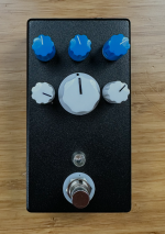
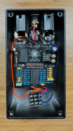
I just built an Arachnid as my first foray into DSP. I am a bit underwhelmed by it honestly. I am assuming it is more about my build than the FV1 as others have done amazing things with it.

My problem is with how the dry and DSP signal come together. The DSP side of things is just not sitting well with the analog signal. Now some of that is definitely due to the relative volume of each. I definitely need to have more volume on the DSP side, but I'm not sure that is all there is to it. Has anyone had a similar experience? and what did you do about it.

If anyone has some measured values across the various ICs that I could compare that would be helpful (I probably should have measured mine before I started this post, I will add that as soon as I get a chance).
 

Attachments

  • IMG_1880.png
    IMG_1880.png
    4.1 MB · Views: 7
  • IMG_1881.png
    IMG_1881.png
    3.7 MB · Views: 9
I believe you could cut the trace between pin 8 and pin 9 on 074, then add a resistor between pin 8 and 9 and also pin 9 and ground.
You can use a calc to set the gain.
This is a non-inverting gain stage.
Using a 1k for both would net a gain of 2, which may be enough.
 
I wonder if there is a way to do that non-destructively. I don’t have the diagram in front of me, but since the 074 is socketed, I could probably bend 8 & 9 out a drop in the resistor and connection to ground.
 
100 ways to Detroit
If you bend the pins and want to reverse it, 50/50 on being able to be d them back AND insert them into a socket correctly.
Conversely, if you cut the trace, you only need to solder blob pins 8 and 9 together to reverse it.
I would just form 1/8w resistors and tack them to the legs.
You could also desolder the header pins on 8 9 so the legs are floating.
But whatever works and feels comfortable.
You may find a gain of 2 is even a bit much. May want to aligator clip the resistor to ground to start. Then you can nudge it if needed
 
Input Voltage: 9.2V

074
Pin 1: 4.45
Pin 2: 4.45
Pin 3: 4.45
Pin 4: 8.90
Pin 5: 4.05
Pin 6: 4.45
Pin 7: 4.45
Pin 8: 4.45
Pin 9: 4.45
Pin 10: 4.41
Pin 11: 0.1
Pin 12: 4.45
Pin 13: 4.45
Pin 14: 4.46

So I am thinking the problem is after the 074 with R19 and R21, If I lower the resistance there I am getting good signal. Problem is I'm not sure why that is happening.
 
Changing R18 will allow some more signal but it will also alter the HPF formed with C12
Stock it's corner freq is 72Hz
Changing R18 to 100R changes it to ~720Hz
Oops, I misread.
You could lower R19 and 21. If that gets you enough change, the good enough.
It's going to alter the feel of the taper of the mix pot. Center won't be 50/50.
 
So, I lowered R9 to 10K brought down R19, R21, R4, and R20 to 10KWhich got me closer, but the I still need to bring the resistance down on R19 and R21 to balance the mix a little better, I will probably need to do something about the B10K mix Pot to make things right.

The thing that I find strange is I can't find anything that is varying from the schematics, and I know people have built this successfully. I doubt they had to play around with tweaking the values so much, I just don't know where I went wrong with this.
 
Back
Top