You are using an out of date browser. It may not display this or other websites correctly.
You should upgrade or use an alternative browser.
You should upgrade or use an alternative browser.
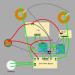
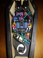
Unconventional wiring grounding and toggles
- Thread starter RobotZombie23
- Start date
RobotZombie23
Member
JohnnyCreepy
Well-known member
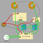
That’s missing pwr gnd reference for pcbs, won’t work as intented.Pretty sure this will work and is cleaner.
Still wondering if that's possible with the toggle though
Your first posts picture is an attempt for star grounding method, but misses one thing about shielding. If going for star-G, the shielding should be with one single common gnd reference and all gnd leads should go to one single point connecting to supply gnd. RG Keen has really nice article about star grounding, look that up. Most of these things are not needed for pedals, but are more crucial for amplifiers.
Edit. I must say on 1st pic, the black block star gnd point could be floating from case/enclosure and therefore appropiate. I like to isolate my jacks and use single separate lead for shielding.
Last edited:
RobotZombie23
Member
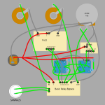
After putting it together I realized the LEDs are always on. This image shows how I should have wired it.(I think)
I can't really modify the switches to fix it. So I'm going to dim or do away with the switch LEDs and make a LED to show if the pedal is in bypass or engaged. I think I can do this using the SW lug
Edit: Changed the image multiple times
I can't really modify the switches to fix it. So I'm going to dim or do away with the switch LEDs and make a LED to show if the pedal is in bypass or engaged. I think I can do this using the SW lug
Edit: Changed the image multiple times
Attachments
Last edited:
JohnnyCreepy
Well-known member
I think using one or two mechanical switches defeats the purpose what relay switching is used for. It’s for 2-3x longer life in use compared to a latching one.
Swtch on pcb could be led pwr out, but without pcb schematic or docs in hand its hard to make more than a guess.
So you want:
-relay for both circuits on/off
-switch for boost/both/fuzz with led indication
To consider:
-Keeping power - and pcb gnds separate until star point (and single lead to power jack -), probably doesn’t matter but one way to ease it is to think signal and power grounds as different streams leading to same river. Makes wiring more tidy too.
-Switching scheme could be done ditching the relay and just using two 3dpt stomp switches. Easy.
-MAYBE keep relay BUT ditch led indication between settings and use on-on-on 3-way toggle (if you cannot hear your toggle orientation…yeah…I won’t continue )
)
-What are the fuzz and boost circuits? Does your fuzz like voost after it? Does it behave? Could you just tweak fuzz circuit output stage to get that missing part of needed gain?
Swtch on pcb could be led pwr out, but without pcb schematic or docs in hand its hard to make more than a guess.
So you want:
-relay for both circuits on/off
-switch for boost/both/fuzz with led indication
To consider:
-Keeping power - and pcb gnds separate until star point (and single lead to power jack -), probably doesn’t matter but one way to ease it is to think signal and power grounds as different streams leading to same river. Makes wiring more tidy too.
-Switching scheme could be done ditching the relay and just using two 3dpt stomp switches. Easy.
-MAYBE keep relay BUT ditch led indication between settings and use on-on-on 3-way toggle (if you cannot hear your toggle orientation…yeah…I won’t continue
-What are the fuzz and boost circuits? Does your fuzz like voost after it? Does it behave? Could you just tweak fuzz circuit output stage to get that missing part of needed gain?
Feral Feline
Well-known member
I'm trying to work out this wiring.
View attachment 101360
You only need one ground on the PCB right? I only need to connect -(negative) OR GND not both?
Also is there any way to use a 3 way toggle instead of two toggles? I'd like:
POS1 Fuzz only
POS2 Both Fuzz and Boost
POS3 Boost only
with LED indicator
Came across this old post today...

Still hoping for some more crazy-switcheroo tadoo from all of you...
Don't forget, the title is Switch-craft, the arcane usage of switches, not to be confused with Switchcraft the brand, which is more involved with connectors than switches, really...
Still hoping for some more crazy-switcheroo tadoo from all of you...
Don't forget, the title is Switch-craft, the arcane usage of switches, not to be confused with Switchcraft the brand, which is more involved with connectors than switches, really...
Feral Feline
Well-known member
I should've mentioned:
- You can swap out the above 3PDT for a relay-based bypass, of course, I'd recommend the PedalPCB smart-relay since it can work as momentary or latching;
- You can use a DPDT on-on-on type II, just gotta re-organise the wiring for that (or take apart the Type II and flip the widget to make it a Type I);
- If you want an order switcher as well, that requires either another 3PDT Toggle (can see which way the toggle is pointing) or 4PDT stomper (extra pole for LED-indication) — order-switcher gets placed between PCBs and A/B/A+B switch.
RobotZombie23
Member
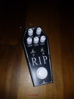
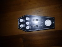
It's a Cream Pie Fuzz and a SHO board from Tayda. In a custom coffin case. I had this wacky Idea for a Coffin case while I wait for Tayda to powder coat. I had all the stuff sitting around to make this. Since I can't take it apart to redo the wiring this is the prototype. I will be making another. Hopefully be done by Halloween 

Attachments
RobotZombie23
Member
BTW Thanks Mr. Feline. I think I had that Switch-craft thread bookmarked but forgot about it 

Feral Feline
Well-known member
Pure gold, there!...
To consider:
-Keeping power - and pcb gnds separate until star point (and single lead to power jack -), probably doesn’t matter but one way to ease it is to think signal and power grounds as different streams leading to same river. ...
Thanks!
I wish that had been described to me a long time ago when I was laying out my own Maestro PS-1 Phaser perf.
Still a tremendous help to me now.


