t1redhands
Active member
Hello!
I'm curious about the use of transistors in chorus schematics, specifically those used in active filters before and after the BBD.
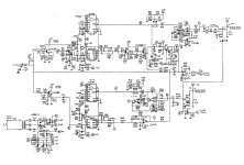
For example, here's an excerpt of Caesar Chorus (Walrus Julia) schematic (link to full schematic):

To my ignorant eyes, these are Sallen-Key filters, usually aiming for a 5kHz cutoff. That much I can ascertain.
But: why are they using BJTs? Even in "new" BBD chorus designs? Does it have something to do with the input/output impedance that makes BJTs preferred in this application over an op-amp?
Some designs have two filters in series for a second-order cutoff effect. Why duplicate the BJT design when an second-order Sallen-Key filter using an op-amp would be more efficient?
Super grateful for any insight into this!
I'm curious about the use of transistors in chorus schematics, specifically those used in active filters before and after the BBD.
For example, here's an excerpt of Caesar Chorus (Walrus Julia) schematic (link to full schematic):

To my ignorant eyes, these are Sallen-Key filters, usually aiming for a 5kHz cutoff. That much I can ascertain.
But: why are they using BJTs? Even in "new" BBD chorus designs? Does it have something to do with the input/output impedance that makes BJTs preferred in this application over an op-amp?
Some designs have two filters in series for a second-order cutoff effect. Why duplicate the BJT design when an second-order Sallen-Key filter using an op-amp would be more efficient?
Super grateful for any insight into this!


