falco_femoralis
Well-known member
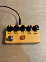
Hi all, today I built this
Starting with the layout

To make this work, the circuit board has to be slightly off center. The best way to accomplish that is to install the 3 pots on the bottom row like so

and leave them a bit loose, but mostly tightened, then fit the circuit board on top, along with the switch. The switch is what we are trying to fit by making the pcb off to one side. When the pcb is in, with the legs of all the pots thru, the switch can be installed while holding the board and applying pressure to make space for the switch

Then solder up the pots while holding the board in place. Starting to populate the wires

Got the LED installed. It's hot glued down

All the wires are on the board. When I off board pots, I use RGB colors and the red wire is always on the square solder pad. This makes it so it's easy to keep track even when the pot is installed in a weird orientation

Installing the power jack. I left just enough room so the retaining nut wedges against the top of the enclosure and essentially becomes a captive nut

Leaving enough slack in the power so I can remove the board if necessary

Alright we're in and the pots are tightened down

Starting with the left pot, I size up the length of its wires and trim them to fit

Now we've got the left audio jack and the right pot in

Everything is in except the switch. I removed the switch and fed the yellow board wires up to the right after this pic

And into their holes on the switch daughterboard with a pair of needlenose. I trim the wire to length and trim the ends of each wire, which is essential for a clean instal into the daughterboard. And that's the wiring done!

Here's the front

My impressions.. definitely less gain than I was expecting. I'll likely have to pair it up with the right guitar and/or right overdrive. But a fun build nonetheless.
Starting with the layout

To make this work, the circuit board has to be slightly off center. The best way to accomplish that is to install the 3 pots on the bottom row like so

and leave them a bit loose, but mostly tightened, then fit the circuit board on top, along with the switch. The switch is what we are trying to fit by making the pcb off to one side. When the pcb is in, with the legs of all the pots thru, the switch can be installed while holding the board and applying pressure to make space for the switch

Then solder up the pots while holding the board in place. Starting to populate the wires

Got the LED installed. It's hot glued down

All the wires are on the board. When I off board pots, I use RGB colors and the red wire is always on the square solder pad. This makes it so it's easy to keep track even when the pot is installed in a weird orientation

Installing the power jack. I left just enough room so the retaining nut wedges against the top of the enclosure and essentially becomes a captive nut

Leaving enough slack in the power so I can remove the board if necessary

Alright we're in and the pots are tightened down

Starting with the left pot, I size up the length of its wires and trim them to fit

Now we've got the left audio jack and the right pot in

Everything is in except the switch. I removed the switch and fed the yellow board wires up to the right after this pic

And into their holes on the switch daughterboard with a pair of needlenose. I trim the wire to length and trim the ends of each wire, which is essential for a clean instal into the daughterboard. And that's the wiring done!

Here's the front

My impressions.. definitely less gain than I was expecting. I'll likely have to pair it up with the right guitar and/or right overdrive. But a fun build nonetheless.
Last edited:
