blazethablunt
New member
Hey everyone, first post here.
I’ve recently released a web application called Vero Designer and thought this would be a good place to share it.
The basic workflow is pretty simple:
Draw the schematic → Generate Vero → Edit the layout
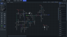
The schematic editor lets you place and wire the components. When a component is selected, you can rotate, flip and duplicate it from the left sidebar. Copy and paste are also available through the regular Ctrl/Cmd+C and Ctrl/Cmd+V shortcuts. For more useful shortcuts, visit the help section.
Available components:
• Resistors
• Capacitors
• Op-Amps
• Transistors
• Tubes
• Diodes
• Potentiometers
• Switches
• LEDs
• Trimmers
• 5v voltage regulator
• Other ICs
Some other useful features:
• Update IDs – Reassigns IDs to all schematic components (schematic page only)
• Update Vero – Applies schematic changes to the existing vero layout without generating a new layout
• Regenerate layout – Generates a completely new layout after major schematic changes
• Auto describe – Generates a description for the layout based on the components used
• Standing resistors – Optional feature to save space, off by default
You can save projects and open them later, give the circuit a name and edit the description. You can also import KiCad files.
Both "Schematic" and "Vero" pages have buttons for undo/redo changes, and export a PNG image. export BOM is available on the vero page.
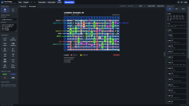
Once the schematic is ready, Vero Designer automatically generates a vero layout. The generated board isn’t locked either. Components, links and cuts can all be edited afterwards.
You can also download the app and use it offline.
For more details, please visit the github page. You will also find a folder with layouts made by me and other users, including some that were built and verified.
Let me know what you think.
Web app: https://verodesigner.vercel.app/
Github: https://github.com/blazethablunt/VeroDesigner
Youtube walkthrough:

I’ve recently released a web application called Vero Designer and thought this would be a good place to share it.
The basic workflow is pretty simple:
Draw the schematic → Generate Vero → Edit the layout
The schematic editor lets you place and wire the components. When a component is selected, you can rotate, flip and duplicate it from the left sidebar. Copy and paste are also available through the regular Ctrl/Cmd+C and Ctrl/Cmd+V shortcuts. For more useful shortcuts, visit the help section.
Available components:
• Resistors
• Capacitors
• Op-Amps
• Transistors
• Tubes
• Diodes
• Potentiometers
• Switches
• LEDs
• Trimmers
• 5v voltage regulator
• Other ICs
Some other useful features:
• Update IDs – Reassigns IDs to all schematic components (schematic page only)
• Update Vero – Applies schematic changes to the existing vero layout without generating a new layout
• Regenerate layout – Generates a completely new layout after major schematic changes
• Auto describe – Generates a description for the layout based on the components used
• Standing resistors – Optional feature to save space, off by default
You can save projects and open them later, give the circuit a name and edit the description. You can also import KiCad files.
Both "Schematic" and "Vero" pages have buttons for undo/redo changes, and export a PNG image. export BOM is available on the vero page.
Once the schematic is ready, Vero Designer automatically generates a vero layout. The generated board isn’t locked either. Components, links and cuts can all be edited afterwards.
You can also download the app and use it offline.
For more details, please visit the github page. You will also find a folder with layouts made by me and other users, including some that were built and verified.
Let me know what you think.
Web app: https://verodesigner.vercel.app/
Github: https://github.com/blazethablunt/VeroDesigner
Youtube walkthrough: