Chuck D. Bones
Circuit Wizard
It was mainly a warning to others. Did you find the warble tone?
Dear all, hopefully someone will pick this up.A little background first. When David Gilmour recorded that famous "seagulls in outer space" tone, the CryBaby had the classic two transistor design. Same as the Tear Jerker, but without the DIP switch and trimpots. The output is taken off of the collector of the 1st transistor. This point is inside the feedback loop that controls the filter freq and it has a high impedance. The high impedance makes it sensitive to loading and the location inside the feedback loop means it could, under the right conditions, lead to oscillation. Guitar pickups are highly resonant and the tone control affects the resonant frequency in a big way. By happy accident, Gilmour discovered what happens when you connect a guitar to the CryBaby's output jack. The entire circuit breaks into oscillation and that signal is present pretty much everywhere. The input jack is one place to pick up the signal, but you could just as well get it from the output jack or other places in the circuit. When I tried hooking my GCB-95 backwards, I got the seagull tone, which surprised me because that design has a 3rd transistor installed as an input buffer. It's the same circuit as the Station Wah. The Seagull tone passes backwards thru Q1. If you want to be able to control the volume of the Seagull tone, then a good place to pick-off the tone is at or near the collector of Q2. I recommend connecting an A500K pot with pin 3 at the board output, pin 2 goes to the Gilmour switch and pin 1 to ground.
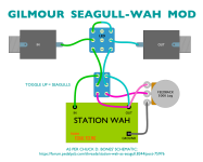
Here are the details of how to do it with the Station Wah. Other CryBaby derivatives such as the Tear Jerker and ShamWah can be implemented in a similar fashion. Only 2 new parts: VR2 and S2.
View attachment 15910
Dear all, hopefully someone will pick this up.
I am considering building this Fixed Wah with a I/O flippy switch (done this before on Vox Wah). I have noted that there is a volume control on this guide but where exactly does each lug on the A500k get soldered too? I have no idea how to read a schematic.
Thanks in advanced.

Dude thanks so much for taking the time to draw this up, it’s super helpful. Will spend a bit of time comparing it to the schematic to rap my head around working it out myself next time.View attachment 94445
3PDT is your bypass stomper.
DPDT can be a 3PDT if you want to add an LED indicator to that, too.
While you could pull the FEEDBACK pot's lug-3 feed from the output jack itself or the 3PDT's output, I wouldn't recommend it — the great thing about the way Monsieur Bones implemented the switching is that if you bump the pot by accident or for whatever reason(s) the seagulls go full Hitchcockian on you, hitting the bypass will kill the gulls' screams.
Thanks man, don’t know if to do a trim nowThanks, Feral. I could see making the A500K pot a 500K trimpot. Once it's set, there's not much cause to change it. Mine is hardwired to a fixed level inside the pedal.
Cheers dude, I’ve ordered some boards whilst there was 15% off. I might even get all fruity and instal an ledI'll suggest a multi-turn trimmer — the screw can rotate fully about 8x, IIRC — perfect for really dialling in the tightest little sweet spot of the pot.
View attachment 94456
They also come with 3-in-a-row legs instead of the tripod depicted above.
View attachment 94458


