Cybercow
Well-known member
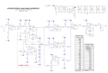
After meticulous tracing both the Rockman (SR&D - gray button) Acoustic Guitar Pedal and the Dunlop Acoustic Guitar Pedal (blue button), and all the heavy lifting in KiCAD for PCB layout work from @rwl, we've accomplished a working PCB for this oldie goldie. We went with the Dunlop blue button version because the JFET biasing scheme is a much easier setup than the gray button version.
After initial testing the first rendition (ver 0.90), I called it a success and built a few out fully. And when A/B'd with both original pedals, this clone is indistinguishable from the originals. (Except for the buffers and low battery indicator sections of the originals.) Since then, @rwl has tweaked it for the final working version - just to jockey some connection points around. (I imagine he'll be posting that info sooner or later.)
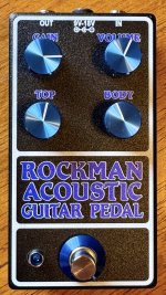
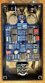
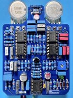
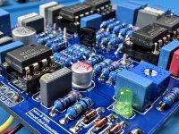
Meanwhile, here are some shots of the finished schematic and build stages. This rendition, (and @rwl's latest 1.00 version), were designed to fit into a 125B enclosure. Hopefully, as time allows and if @rwl is so inclined, a 1590BB sized project will be done up so the control pot layout will match the original pedals.
