Season's Gratings...
After Christmas-Eve dinner at friends, upon returning to the abode I sequestered myself to put something together.
I'd just like to note that I HATE putting in subs and fixes — If the build calls for a 1µ Electro, then that's what I want in there. Stuff doesn't get built 'til the correct parts come in.
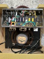
Alas, the urge to build over-rode the OCD-behaviour and work commenced on this VFE SPS Yodeler.
View attachment 108290
Missing:
1k 1/8w
10k 1/8w
Assorted cap values *(many)
Resistor Array
I scrounged, scoured and scraped everything together, except the resistor array.

In fact, most of my time was spent on work-arounds and things like those blue caps near the PT2399's socket — those were from Electronic Goldmine, and most were way out of spec, but out of a couple dozen, I found two that were the correct 82n. It's just the filtering for the PT-chip, I could've gone for the DELAY value of 100n instead of the ECHO's 82n, but... Ennnyhoohah, the blue buggers saved me from wiring 470n and 100n in series (82n456), or 47n+33n in parallel (80n & add another 2n? SPACE?!) and other odd concoctions trying to hit the target. One of the first five blueies measured 82n, then I had to keep measuring and the third-last one was also 82n — the only two 82n amongst a couple dozen ranging from 76 to 92.
I kept coming up against road-blocks, 100n caps with pF-sized footprints. Found my bag of bent-legged 100n such devices in the miscellaneous scrap pile of Electronic Goldmine stuff. EG to the rescue yet again.
The 10k resistors were made from TeePee-ing 9k1 and 910Ω resistors.
The 1k resistors were made from bridging 910Ω and 91Ω resistors.
That blue fat 100µ cap should suffice, but I tucked a 47µ under it in parallel because the build is supposed to have a 150µF cap there.
The trimmers I had didn't fit, too big. Went through all my parts drawers until I found the correct type 10k... Subbed in 1µ tants for the called-for electrolytics.
Couldn't find any BS170, so for this one lone part is the only one I pulled from another build — Good thing I like SOCKETS!
(But I soldered it into the Yodeler.)
So, somewhere in a drawer is a small handful, probably not even a half-dozen, resistor arrays. No idea if they're the correct value or not, if I can even find them.
The enclosure's drilled, everything is just hanging on that resistor array now.
BTW, does anybody know that the "BBD" resistor footprint is about. Whatever it is, I noticed it's not populated on
@jjjimi84's Yodeler.
Hope you're all having as much fun as I am! SEASON'S GREETINGS people!
PS: looking into making my own resistor array (1/4w 10k resistors)


 www.globalindustrial.com
 (why always the expensive parts?).


.png")