wiring issues trying to add an extra blend circuit in an overdrive build

eh là bas ma

Well-known member
Hello,

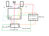
Im trying to build Aion's Fractal with a "Blend me up" circuit.


The Blend Me Up circuit came with its own 3PDT pcb, as shown in the instruction.

I dont want to use the Blend me Up 3PDT pcb, just the main pcb where the pot is located,
because with Aion projects, i need to use Aion 3PDT pcb.

Is that even possible ?

In my first wiring attempt, the status led doesn't even light up.

Between Aion's 3PDT pcb, and that extra wet/dry mixer circuit, im getting confused with the wiring, especialy with the 9V+ pads.
fractal.png
Screenshot 2026-03-26 at 02-25-17 FCP-Blend-Me-Up-Insert-V1-0.pdf.png
Did i make many mistakes ?

All observations and suggestions are welcome !
 
Last edited:
I don't think you can bypass the blend circuit without the switch as it becomes the new bypass and works between the aion board and the jacks
You'll have to hack it in with the aion daughter board for it to work
 
I think the power jack connections goes to the center of the aion daughter board. Then after power protection it goes out to the board at the left. If you feed 9v on the left connection, the reverse diode will stop the current.
 
I don't think you can bypass the blend circuit without the switch as it becomes the new bypass and works between the aion board and the jacks
You'll have to hack it in with the aion daughter board for it to work
Thanks for your reply !

Looks like the DC jack positive leg's connection was bad, i managed to power up the circuit.
I also modified the wiring a bit
fractal.png
The Blend pot works, but the dry volume level is low compared to the wet volume.
And the trimmer on the mixer circuit doesn't have any effect, although i guess it should be a volume control for the dry signal.

Not sure if it's related to the empty +9v and GND pads on the blender pcb

I do have some voltage readings on the 2N5457

Assuming the square pad is D, it reads :

D = 9.46V
S = 5.15V
G = 4.45V

Turning the trimmer fully CW or CCW doesnt affect the readings.
I'm guessing it should affect the readings ?
 
Did you try the trim pot at full dry and full wet ? From the doc it should affect the "out" volume. Is there a schematic ?
 
Sounds like it only affects the overall volume, or maybe it boosts the wet signal when i turn the trimmer CW.

It's not just louder, it's also more saturated, with more highs with the trimmer fully CW

It doesn't increase the clean signal by itself, like i would expect.

But with the trimmer fully CCW, the volume gap between fully clean and fully wet is significantly decreased
 
So the trimmer increase the blender output volume
and this output volume goes into the Fractal overdrive circuit
so i guess it's going to boost it...

but i think it's weird that it doesn't also increase the clean volume, when the Blend control is fully CW, set on full clean signal ?
 
Anyway, looks like i can put that blender to good use, when the trimmer is set at low value.

And i also need to understand how the Fractal works, it's the first time i build this circuit.

Thanks for your help !
 
Last edited:
  • Love
Reactions: Nic
So the trimmer increase the blender output volume
and this output volume goes into the Fractal overdrive circuit
so i guess it's going to boost it...

but i think it's weird that it doesn't also increase the clean volume, when the Blend control is fully CW, set on full clean signal ?
I think the trimmer is there to set the wet volume to your liking, depending on your preferred settings on the fractal. But the buffer could affect the sent signal maybe? How about phase inversion ?
 
Im not sure i really understand what's happening between these two circuits, and i was probably wrong in post #9.

And maybe it's a good exercise for beginners in audio electronics

From what i experience with this wiring setup (see attached files),

The first part of the Blender circuit from C1 to Q1 is buffering the signal before going into the overdrive circuit,
without the Blender 3PDT bypass switch, i cant turn it off.
Yet the build is still true bypass, if i unplugg the power cable it still passes signal when it's switched off.

The trimmer isn't biasing the FET transistor like i thought at first glance,
it's allowing to add resistance between the Fractal circuit output, and the Blender output, right ?

I turned that trimmer fully CCW to lower the overdrive signal volume, in order to get more usable sounds and a better range of action from the Blend control, with a better clean/wet ratio.

But if i am not mistaking, i need to turn the trimmer fully CW and get it to 0 resistance if i want the original overdrive volume.

When they say we can adjust the Blender's output volume with the trimpot, they really mean we can decrease the main circuit's volume.
We cant increase it, and we cant affect the clean signal with the trimpot.

Am i wrong ?
 

Attachments

  • fractal.png
    fractal.png
    18.5 KB · Views: 2
  • Screenshot 2026-03-26 at 03-51-59 Printing Print Schematic - FCP-Blend-Me-Up-V1-0-schematic.pdf.png
    Screenshot 2026-03-26 at 03-51-59 Printing Print Schematic - FCP-Blend-Me-Up-V1-0-schematic.pdf.png
    43.1 KB · Views: 2
I had about the same experience adding a buff n blend on an aion board (polaris), lots of trials before getting it to work.

That one does not have the trimmer... so I'll let others more experienced explain it. My first thought is it's function is to set the level (volume) of the signal sent to the effect so it matches the dry blend.
 
The FCP Blend Me Up and the GPCB Buff N Blend are the same circuit. Said circuit is known by a myriad of names such as Split n Blend (though I've also seen a two-transistor "Split n Blend") and other monickers — yet the core circuit remains the same.


The only differences I see between the FCP and GPCB versions are the cap values, transistor choice and pot values; to reiterate: the bones are the same.

I have a few of the GPCB boards and have subbed out its R5 for a pot, as per the FCP's "Level1".
If I need it again in future, wired as a rheostat, I'd use one of PedalPCB's Trimmits. They make it easy to sub in a trimmer for a resistor.

Trimmit-510x612.jpg


Regarding Level1, it does not set the volume of the signal sent to the effect — it is there to attenuate an overly hot signal coming back via the return, such as an over-gained mhêtåhl füzz.


If you find the buffered signal of the SEND is overpowering the input of an effect in the loop (say, for example, a modulation pedal that's distorting harshly in a bad way), you could add another pot on the SEND wired either as a rheostat or as a voltage divider:

RHEOSTAT
BnB/BMU SEND > lug2 of pot,​
lug1 > output to effect from lug1 (lug 3 unused or SEND to lug3 and jumpered to lug2, output to effect still from lug1)​

VOLTAGE DIVIDER
SEND > lug3 of pot​
lug2 > effect​
lug1 > minimum resistance resistor — so you don't kill the signal completely when set at its lowest (or lug1 to effect, if you do want the ability to kill that signal completely)​


Personally, since it's just a buffer I'd use a J113 for the transistor (closest thing to the now obsolete MPF102), save the 2N5457 transistor for other builds that require it (phasers, AIAB, etc).
Adjust caps and pot values to taste.


buff-n-blend-schematic-png.91012
Thank you @Feral Feline ! Love the explanation. 😻
 
Back
Top