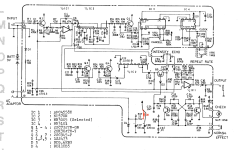
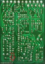
I want to make a Boss DM-2 on a PCB near to the size of the original. What size of resistors did they build into the original pedal? Was it 1/4W or 1/8W? I want to make sure I won't run out of space before starting to build. Moreover from 1% tolerance resistors I only have 1/2W type, I guess those might be too big for this purpose.

You are using an out of date browser. It may not display this or other websites correctly.
You should upgrade or use an alternative browser.
You should upgrade or use an alternative browser.
Boss DM-2 what resistor sizes needed?
- Thread starter geso
- Start date
The MBP Aquababy uses 1/8w, but it also fits in a 1590B, which is a bit smaller than a boss pedal.
The Amethiyst Delay is a "reiterpretation" of the old pedal so to say. It has a detailed building instructions pdf but that also seem to lack that info. Meanwhile I checked that 1/4 may not fit to be oriented horizontally, but according to photos of the original board, several resistors are aligned diagonally there as well. So maybe I will stick to 1/4. Sideways there seems to be enough room for those too.
1/8W is perfectly fine. 1/4W will probably have a slightly lower noise threshold, but that is true for any bit of audio electronics. However, the DM2 itself already has a lot of noise suppression built into the design via the compander.
Thanks!
However, meanwhile I noticed a problem with the PCB I found to be available. It is the PCB for the first version that uses the MN3005 chip, but 2 things do not match. It seems as if those are not an error, but were added for some reason, there is just no info why:
1. There is an extra diode added, that was only present on the last version:
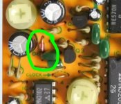
It is not on the original first version:
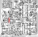
Why was that added?
2. A component named CF was also added, but have no clue why. Maybe a LED? Originally the led is not on those legs. The CF connects to 10 and 8, but the LED is originally on 14 and 9.
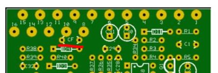
It is not on any version of the pedal:
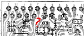
There is no BOM for the available PCB, so I have no idea what this thing is. Do you have a clue?

bean
Legume Liaison
I'm not totally sure about that extra diode, but my guess is it's being used for ground isolation on pin3 of the MN3102 in the later design. So, a little extra insurance to prevent any ground loops or possible clock noise. IOW, the diode prevents any stray current present in DC ground getting to the clock.
The CF labeled cap might be additional clock filtering. I'd have to go back and look at the different schematics available. But, I almost certain these are small tweaks that do not represent any significant change in design.
The CF labeled cap might be additional clock filtering. I'd have to go back and look at the different schematics available. But, I almost certain these are small tweaks that do not represent any significant change in design.
Thanks for the info! Meanwhile I have drawn the diode mod into the schematic you can find below, maybe that one tells more (drawn with red). The last version of the PCB has this extra diode added with the exact same modification of the routes. But as mentioned, the first version that I am trying to make doesn't have it. The CF is not drawn on this, but it connects cable solder points 8 and 10 basically.I'm not totally sure about that extra diode, but my guess is it's being used for ground isolation on pin3 of the MN3102 in the later design. So, a little extra insurance to prevent any ground loops or possible clock noise. IOW, the diode prevents any stray current present in DC ground getting to the clock.
The CF labeled cap might be additional clock filtering. I'd have to go back and look at the different schematics available. But, I almost certain these are small tweaks that do not represent any significant change in design.
If you don't mind I'd ask some more things, maybe you have a clue about the answer:
1. Are those diode D1 and R2 that need to be removed to be able to use this pedal with modern balanced 9V PSU?
2. The AI noted that at some sections the widened traces was for providing enough copper in case spikes are generated in the circuit, that this design is prone to do (you can see those traces on the second photo below). Normally this is done by ground fill or extra ground traces on the top of the board nowdays, but back in the 80's as the board had copper on 1 side, this is how they solved grounding. This is how they tackled clock noise and ground bounce. But other AIs claim this is not so. The problem is that the pbc available for this pedal to order has the exact same drill hole locations as the original, but the traces are thin and uniform. I wonder if that will cause noise issues indeed?
3. Another suggestion that I found as a useful mod was to add a 100nF ceramic capacitor between lugs 1-3 of the clock chip, or between its lug nr. 1 and ground. Is that useful indeed?