- Build Rating
- 5.00 star(s)
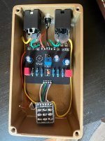
This build was a nice change of pace from my last one, which was a Cornish clone with a packed pcb. This one has just a few parts and came together quickly. I wanted to try this one badly enough that I was willing to try soldering an SMD transistor for the first time. It was not as scary as I thought it would be and went on fairly easily once I found the right tweezers for holding it. I didn't want the hassle of soldering on legs to test the transistors' values in my TC-1 so the first one out of the pack is what made it onto the board. Even with the trim pot at max I could only bias to 6.0V but the pedal still sounds great. I thought that lone solder point was a joke from @Robert so I soldered in my trim pot at an angle to get at the testing points near it. After it was in it soon became clear that the lonely little pad is for measuring the voltage, something that would have been obvious if I actually examined the PCB before I got to soldering.
Because populating the board only took a few minutes, I had plenty of time to think about the best ways to do the jacks, wiring, etc rather than racing through that part before I have to get back to doing something important. I came up with a system I like that made the final assembly much easier than my past builds and so I'll be trying that going forward.
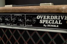
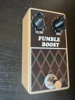
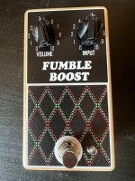
I wanted the pedal to look like the suede covered ODS in the picture. It's a Dark Champagne 125B from Tayda with a UV print and I'm happy with how it came out. The complexity of the artwork vastly exceeds that of the circuitry inside.
In terms of how it sounds, I'm struggling to describe it without anathematized buzzwords like "texture," "clarity," "sparkle," etc. It definitely seems like its doing something besides adding more clipping and is a very nice sounding clean boost. It's paired well with a number of overdrives and I think it will be staying on the board for a while. Highly recommended.
Because populating the board only took a few minutes, I had plenty of time to think about the best ways to do the jacks, wiring, etc rather than racing through that part before I have to get back to doing something important. I came up with a system I like that made the final assembly much easier than my past builds and so I'll be trying that going forward.
I wanted the pedal to look like the suede covered ODS in the picture. It's a Dark Champagne 125B from Tayda with a UV print and I'm happy with how it came out. The complexity of the artwork vastly exceeds that of the circuitry inside.
In terms of how it sounds, I'm struggling to describe it without anathematized buzzwords like "texture," "clarity," "sparkle," etc. It definitely seems like its doing something besides adding more clipping and is a very nice sounding clean boost. It's paired well with a number of overdrives and I think it will be staying on the board for a while. Highly recommended.