

Locrian99
Well-known member
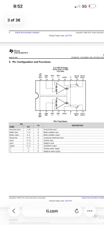
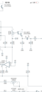
So looking at the datasheet this appears to be internally connected but both of these schematics have me questioning this somewhat.

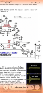
Theres not a pin that available so I’t got to be internally connected. It just seems weird they’d label it v+ and I don’t see a “G” in the valve wizard schematic for that to be connecting to. Before I layout and order pcbs just want to make sure I’m not missing something.
Theres not a pin that available so I’t got to be internally connected. It just seems weird they’d label it v+ and I don’t see a “G” in the valve wizard schematic for that to be connecting to. Before I layout and order pcbs just want to make sure I’m not missing something.

