Fuzz Face with variable Miller Cap

zakco

Member
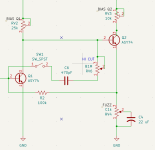
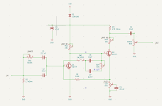
I'm working on an NPN Fuzz Face with a fully variable input filter (from the Chickenhead) and I'm trying out a similar approach as a fully variable LPF using a pair of miller caps across Q1's base and collector and a pot that wipes between the 2 values. I've settled on a 10pf and a 2.2 nF (C6/C7). When the pot is fully clockwise (10pF) , the HF response is pretty much unaffected in the guitar spectrum and when it's counter-clockwise (2.2nF), it's extremely rolled off. I'm quite happy with the range that this produces and I've included an on/off switch that takes the caps out entirely. The result is essentially a stock Fuzz face when the input is wide open and the caps are switched out. When the input filter is turned up, it sounds less like a fuzz and becomes a really great distortion. The only downside is that when the lows are filtered out and the fuzz is turned down and volume turned up for unity gain, the treble range can become a bit overbearing, which is where the Miller caps can be engaged as a fully variable LPF. I'm guessing it's a crude approach to EQ, but it works and is less lossy than every other tone control I've tried on a Fuzz Face.

My question:

For RV6, I experimented with various pot values and I noticed that the higher the value, the less volume loss occurred. I ended up at 1 mOhm because that's the largest value I have on hand. Would the volume loss be even less if I ordered a 2mOhm pot? I understand how the miller cap value affects the corner frequency, but please help me understand the role that the pot's value plays in this?

Thanks!
 

Attachments

  • HANDFLOWER FUZZ_260912.png
    HANDFLOWER FUZZ_260912.png
    63.2 KB · Views: 26
More resistance in this context is more resistance to negative feedback. Less feedback means more gain and high frequencies! There will always be some current flowing through both Miller caps, even at the brightest setting. A sufficiently large resistance will make the "bright" setting indistinguishable from disconnecting the Miller caps entirely. What that resistance is depends on countless variables. You could test with different resistors and see if it's worthwhile to use a larger potentiometer. In most guitar circuits 1M is enough to act like a brick wall for signal.
 
  • Like
Reactions: spi
More resistance in this context is more resistance to negative feedback. Less feedback means more gain and high frequencies! There will always be some current flowing through both Miller caps, even at the brightest setting. A sufficiently large resistance will make the "bright" setting indistinguishable from disconnecting the Miller caps entirely. What that resistance is depends on countless variables. You could test with different resistors and see if it's worthwhile to use a larger potentiometer. In most guitar circuits 1M is enough to act like a brick wall for signal.
That's really helpful, thanks!
Another beginner question...
The pot is wired with lug 3 > C6, lug 2 > lug 3 and lug 1 > C7. If I were to replace the pot with a larger, fixed resistor for testing, how would I wire it to compensate for the missing point (lug)?
 
Last edited:
If the idea is to make the brightest setting brighter, you could strap the 10pF capacitor across the collector and base (which is electrically equivalent to your current arrangement). In parallel to that, connect collector to resistor to capacitor to base. That arrangement is electrically equivalent to the darkest setting. Then test resistors to see which value you like.

All that said, you could also get a brighter bright setting by ditching the 10pF capacitor entirely, but honestly, I usually don't hear much of an effect with caps smaller that 47pF in this kind of arrangement, so there may not be much in it.
 
If the idea is to make the brightest setting brighter, you could strap the 10pF capacitor across the collector and base (which is electrically equivalent to your current arrangement). In parallel to that, connect collector to resistor to capacitor to base. That arrangement is electrically equivalent to the darkest setting. Then test resistors to see which value you like.

All that said, you could also get a brighter bright setting by ditching the 10pF capacitor entirely, but honestly, I usually don't hear much of an effect with caps smaller that 47pF in this kind of arrangement, so there may not be much in it.
Sorry, I should have been more clear in regard to my intent!
I'm not trying to make it brighter, I'm trying to eliminate the slight loss in volume that happens when the switch is engaged, even when it's at the smallest (brightest) value (10pF). When I was experimenting with pot values, the volume loss became less apparent as the value got larger and my largest cap is 1mOhm. I'm wondering if increasing that value further will eventually eliminate the volume loss of if I've already reached the limit of that with 1mOhm?
 
Negative feedback will always cost you gain. At some point, the loss will become negligible. I'd still try using the arrangement I described above. You could switch between the resistor/cap and the open switch to compare.
 
Last edited:
Negative feedback will always cost you gain. At some point, the loss will become negligible. I'd still tear using the arrangement I described above. You could switch between the resistor/cap and the open switch to compare.
After experimenting with several resistor/cap combinations I have come the conclusion that I have been overthinking this! I removed the second cap altogether and settled on a single 470pF and the 1mOhm pot and the gain loss is pretty much negligible now with a very usable sweep. I attached an updated schematic to demonstrate. This was an excellent learning process and I appreciate your help, thanks!
 

Attachments

  • Screenshot 2026-09-14 at 11.49.56 AM.png
    Screenshot 2026-09-14 at 11.49.56 AM.png
    41.7 KB · Views: 6
Back
Top