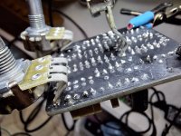
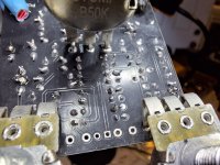
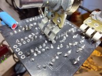
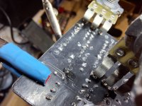
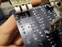
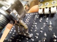
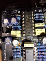
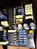
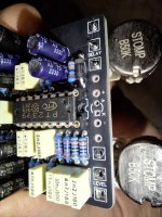
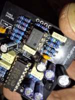
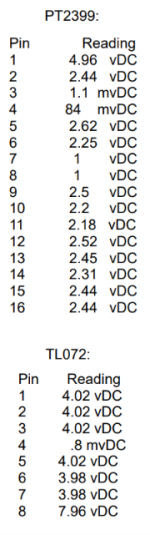
This is my first post to the forum, I'm building a Seabed Delay kit and have populated the PCB after a successful breadboarding of the circuit. I'm at the point of testing out of the box and am running into a problem with the Level knob controlling the amount of Repeats.
I've probed and tested until I was out of ideas so I thought I'd bring it to the hive mind to see if anyone could help. Below is a video of the issue, a sweep around the solder-side of the board, and some pictures.
Thank you and let me know if I've forgotten any important information. I can take more pictures if needed.
Man, I must be running myself in circles chasing gremlins. I was going off of multimeter readings of R15 (while soldered in of course) and my bad eyesight. Good thing I have those pictures
I've found the culprit by narrowing it down and I cant believe I didn't try the last thing first. You always find it in the last place you look, amirite?
With all of the probing that I've done including audio probing last night, I've narrowed it down to it not being in the audio path at all.
Next I checked for fluctuations in voltage when moving the volume knob but that wasn't it.
Then I checked for a grounding issue, and lo and behold the circuit wasn't truly grounded to my jack. Once it was, I got my glorious single repeat with the volume...
Its been awhile since ive played this circuit. But the level knob controls the level of the repeats from the description and that sounds like what is happening to me. You’re hearing more repeats because the level of the repeats also bring quieter repeats to be audible? Maybe i’m wrong as i said its been awhile since I’ve played the circuit.
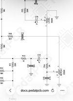
Edit: in the schematic you see the level knob is set up as a volume knob in the delayed path only. So I think its working as intended.
Its been awhile since ive played this circuit. But the level knob controls the level of the repeats from the description and that sounds like what is happening to me. You’re hearing more repeats because the level of the repeats also bring quieter repeats to be audible? Maybe i’m wrong as i said its been awhile since I’ve played the circuit.
Edit: in the schematic you see the level knob is set up as a volume knob in the delayed path only. So I think its working as intended.
Hey, thanks for the reply. I understand what you're saying, but that's not quite how it worked on the breadboard when I had it configured. This is actually adding more repeats when the volume is raised higher. I've never come across any delay that has behaved this way. I remember specifically being able to get one single repeat at a high level of delay volume as seen in the video below:
If I turn down the repeats and the level all the way up I almost go into oscillation.
Hey, thanks for the reply. I understand what you're saying, but that's not quite how it worked on the breadboard when I had it configured. This is actually adding more repeats when the volume is raised higher. I've never come across any delay that has behaved this way. I remember specifically being able to get one single repeat at a high level of delay volume as seen in the video below:
If I turn down the repeats and the level all the way up I almost go into oscillation.
I've been poking around on this more and more, reflowing, probing, pulling resistor legs to roll values, and relying on our Ai overlords to help me with ideas while I scratch my head at this. The three potentiometers are all testing fine and I have the board with its chips pulled and drying out after a wash in contact cleaner. Going to test some socket pins next.
Visually, all the part values that I can see look correct (harder to see values on electrolytics). So good job there.
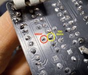
My comment would be to use LESS solder. You want enough to connect them, but adding more isn't necessarily better - too much can obscure whether the solder has fully wet the part and/or PCB, which can lead to undesirable contact resistance or even a capacitive connection. You want the solder to flow smoothly, to wet the surfaces of both the PCB and the part's lead - thus giving a concave surface.
Many of your solder joints look that way, which is great. But some have too much solder and I can't see whether the solder has fully wet the PCB. See the picture I attached below, with comments.
Visually, all the part values that I can see look correct (harder to see values on electrolytics). So good job there.
My comment would be to use LESS solder. You want enough to connect them, but adding more isn't necessarily better - too much can obscure whether the solder has fully wet the part and/or PCB, which can lead to undesirable contact resistance or even a capacitive connection. You want the solder to flow smoothly, to wet the surfaces of both the PCB and the part's lead - thus giving a concave surface.
Many of your solder joints look that way, which is great. But some have too much solder and I can't see whether the solder has fully wet the PCB. See the picture I attached below, with comments.
Awesome, thank you for the feedback. I'll see if cleaning those up helps. Just got one of those PCB holding jigs from Amazon to make it a little easier
It’s pretty odd behavior for sure. I think you’ll just need to check for the right continuity (and make sure there’s not unwanted continuity) in this area of the circuit. Study how the signal path is supposed to be flowing.
If the repeats knob is all the way down, then lug2 should beep to ground (since lug1 is ground). This would mute the signal on its way back to mix with the input (through R10). So I wonder if somehow lug1 isn’t connecting to GND, or if you have a bad pot.
But I’m not sure if that fully explains the behavior of the LVL knob increasing the repeats. For that to happen it seems like there’s an unwanted connection after LVL lug2 to the C11/R10 feedback line.
It’s pretty odd behavior for sure. I think you’ll just need to check for the right continuity (and make sure there’s not unwanted continuity) in this area of the circuit. Study how the signal path is supposed to be flowing.
If the repeats knob is all the way down, then lug2 should beep to ground (since lug1 is ground). This would mute the signal on its way back to mix with the input (through R10). So I wonder if somehow lug1 isn’t connecting to GND, or if you have a bad pot.
But I’m not sure if that fully explains the behavior of the LVL knob increasing the repeats. For that to happen it seems like there’s an unwanted connection after LVL lug2 to the C11/R10 feedback line.
I've done a bunch of probing, concentrating on this exact area specifically. Most of my time is late into the night after work hours so I'm pretty taxed by then. My notes are scattered but here is what I've mustered so far:
Repeat pot:
Knob fully CCW, probes on lugs 1 and 3 read 51.8k ohms.
Knob fully CW, probes on lugs 1 and 3 read 27k ohms. Should this read 0 or near 0?
Knob fully CCW, probes on lugs 1 and 2 read 1.5 ohms.
Knob fully CW, probes on lugs 1 and 2 read 27k ohms.
Knob fully CCW, probes on lugs 2 and 3 read 51.8k ohms.
Knob fully CW, probes on lugs 2 and 3 read 1.3 ohms.
Lug 1 has continuity to ground.
Lug 2 has continuity with my 2k resistor (measures 1.9k) in R14 and 47n cap in C15.
Lug 3 has continuity with C11.
Level pot:
Knob fully CCW, probes on lugs 1 and 3 read 27.14k ohms.
Knob fully CW, probes on lugs 1 and 3 read 27.14k ohms.This seems off? as i rotate the knob the number falls to 27.11k before jumping back up to 27.14 at the very end of the rotation
Knob fully CCW, probes on lugs 1 and 2 read 1.5 ohms.
Knob fully CW, probes on lugs 1 and 2 read 27.14 ohms.
Knob fully CCW, probes on lugs 2 and 3 read 27.14k ohms.
Knob fully CW, probes on lugs 2 and 3 read 1.7 ohms.
Lug 1 has continuity to ground.
Lug 2 has continuity with C14 neg.
Lug 3 has continuity with C13 neg and R14.
Other Notes:
R14 = 1.9k
Caps 10, 11, 14, 15 checked and correct.
Repeat Lug 2 and Level Lug 3 have no continuity.
I disconnected the R14 Leg that connects to C13 neg and Level pot Lug 3. Reapeat pot became inactive, Level pot still controlled Level and Repeats.
Level Lug 2 and Repeat Lug 3 with knob full CW read 53k. This includes the pot track and R14, I assume?
Grounding the Repeat wiper kills runaway oscillation.
Repeats remain with Repeat Lug 2 grounded.
R10 leg away from C11 and Level Lug 3 read open.
R10 leg away from C11 and Level Lug 2 read open.
C14 neg lifted: No wet signal
With Repeat pot fully down and level fully up, probe on R10 away from C11 and probe on GND. AC reading with no signal is .029v. with a Small audio signal input, i got an AC reading of .104 with level knob up. Level knob down and i get nothing.
Lug 1-3 is the full Resistance of the pot. It doesn't really change when you move the pot. (Only the resistance from 1-2 and 2-3) changes. With the pot out of the circuit, 1-3 should always read 50k. In the circuit, there's 2 resistance paths from lug3 to lug1(gnd): Through the Repeats pot (50k), and through the R14 then the level pot (52k). In parallel, this comes to about 25.5k, which is fairly close to what you're seeing. This same concept applies to your LEVEL lug1-3 measurement.
I disconnected the R14 Leg that connects to C13 neg and Level pot Lug 3. Reapeat pot became inactive, Level pot still controlled Level and Repeats.
yeah but it depends on the position of both pots, as it could go through both pot tracks depending on their positions.
I guess I would try removing (or lifting a leg of) R10, to see if the cross-talk from the wet signal (after LEVEL lug2) back to the input is coming before or after R10. I know you read open from R10 to the level pot 2&3, but the C11 would block any reading of resistance or continuitiy.
It seems there's a bridge between the pads at C15 with the cap pulled. I'm getting a little over one ohm reading. This was late last night so I didn't have too much time to dig in. Slow and steady!
It seems there's a bridge between the pads at C15 with the cap pulled. I'm getting a little over one ohm reading. This was late last night so I didn't have too much time to dig in. Slow and steady!
what position was the Repeats POT? If all the way down, then it would show that result due to lug1-2 being basically connected.
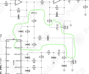
C15 is before the Repeats Pot. Your symptoms strongly indicate a connection somewhere in this area. The delay signal (after Level Lug2) is getting back to that pin15-16 input to the delay chip. If you pull R10, you can deterimine if the cross talk is before or after that point.
what position was the Repeats POT? If all the way down, then it would show that result due to lug1-2 being basically connected.
C15 is before the Repeats Pot. Your symptoms strongly indicate a connection somewhere in this area. The delay signal (after Level Lug2) is getting back to that pin15-16 input to the delay chip. If you pull R10, you can deterimine if the cross talk is before or after that point. View attachment 127223
Ah yes, I should have mentioned that I did pull up a leg of R10 - I posted this morning without looking at my notes from last night. After doing so, the delays weren't as "heavy" as they were with the R10 leg connected, the Level knob is still adding to the amount of repeats.
What I was doing after that was checking the voltage between Level Lug 2 and downstream components. Upon checking either leg of C15 I was getting 13.5K at both and assumed I should have read 0 or open. I'm sitting in my car about to head to work so I don't have my notes in front of me at the moment
It's odd that R10 would have a partial effect. The delay signal is leaking into the feedback signal somewhere. If lifting a leg of R10 resulted in a decrease of the repeats, but not an elimination of repeats (with REPEATS knob off), then that would indicate there were 2 leak points, and lifting R10 solved one of them. That's surprising, if all your testing was consistent.
Unfortunately you won't be able to lift the other components (such as R7 R8 R9) without messing up the initial signal input to the delay.
Man, I must be running myself in circles chasing gremlins. I was going off of multimeter readings of R15 (while soldered in of course) and my bad eyesight. Good thing I have those pictures
I've found the culprit by narrowing it down and I cant believe I didn't try the last thing first. You always find it in the last place you look, amirite?
With all of the probing that I've done including audio probing last night, I've narrowed it down to it not being in the audio path at all.
Next I checked for fluctuations in voltage when moving the volume knob but that wasn't it.
Then I checked for a grounding issue, and lo and behold the circuit wasn't truly grounded to my jack. Once it was, I got my glorious single repeat with the volume knob cranked to maximum. Huzzah!
Now that the circuit is solidly grounded, the feedback path has a true exit rather than using the Level pot into a secondary feedback driver.
My ignorance has really gotten me familiar with this ins and outs of operational amplifiers and these PT2399 chips. I've stumbled onto some cool pitch shifting ideas and perhaps some interesting reverbs as well, and I have a few more chips to experiment with.
Thank you so much to @phi1 for throwing your brain at this issue I had made for myself and to @Locrian99 and @darwin999 for taking a look!
Congrats @Alex Kenivel ! Troubleshooting takes persistence, and you have it! And it also actually helps you more deeply understand the circuit. Keep on building!
Nice job on the fix! A quick tip when soldering is after feeding solder into the joint, instead of pulling the iron away and letting the solder sit there, run the tip of the iron up the lead of the component. Excess solder will wick to the component leg, while leaving just the right amount at the joint where you want it.