This Week on the Breadboard: A Stereo Digital Reverb

Chuck D. Bones

Circuit Wizard
I took a break from working on the BBD reverb to explore the possibilities an improved version of the Belton Brick. I came across Brian Thornock's T60 reverb and that looked like a good place to start. Check out his website, he has a few reverb projects there. The T60 uses four, count 'em, four PT2399s. The T60 is based on the Belton design, but goes much further in the quest to build a realistic sounding reverb. One of the features of the T60 is a SIZE control that varies the delay in two of the four PT2399 so the user can vary the size of the "room" in which reverberation takes place. The T60 also has a MIX control and a DWELL (feedback) control. To keep the delay from sounding sterile, Brian used two LFOs running at different speeds to modulate the clocks in the two longest delay chips. Very effective and unlike the Belton, it doesn't sound cyclic. In another of his reverb designs, he uses the envelope to modulate the clock and that works even better. Turns out that pins 7 and 8 on the PT2399 have signals on them that follow the envelope of the signal passing thru the chip. Brian's schematic was hard for me to read, so I redrew it and made mods from there. I fiddled the resistor values a bit, changed a couple of connections and wired it for mono-in, stereo-out (similar to the Belton's two outputs). Even my cleaned-up schematic is hard to digest because there are so many signal paths. The guitar signal comes in and is mixed with the feedback (DWELL) signal and then sent out to all four PT2399s. Like the Belton design, the outputs of all four chips are mixed together and sent back out out to all four chips. All four chips have local feedback as well. Basically, each delay chip has three inputs: the dry input signal, local feedback from itself and global feedback from all four chips. All of these paths create dozens of reflections. Each chip has a different delay ranging from 48ms to almost 400ms when the SIZE control is dimed. The REVERB (blend) control goes from 100% dry to 100% wet. When the DWELL control is dimed, the thing breaks into self-oscillation. I didn't have a B100K dual pot for the REVERB control, so the breadboard has two blend controls, one for the Left channel and one for the Right. The white box on the left is my stereo headphones amp. Controls from L to R are Left REVERB, Right REVERB, DWELL and SIZE. Brian used a dual pot to vary the clocks on two chips. I found that it can be done with a single pot. The four PT2399s are in the top row, with the output mixer / buffer at the far right. Below that is the 5V regulator. The input buffer is at the bottom right. This is the cleaned-up layout and it is still quite the spaghetti factory.
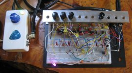
Stereo Reverb v0.4 - 02.jpg
 
Last edited:
I'm almost afraid to ask for a schematic. Is there any volume drop or is there unity gain throughout?
Pretty close to unity, I might need to tweak one or two resistors.

I’m really curious to see the schematic.
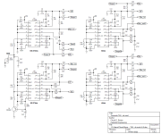
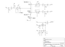
Here is the as-built schematic. The only thing that's different on the breadboard is the REVERB pot (VR1) is ganged on the schematic, but two separate pots on the breadboard. I might fiddle a few resistor values, but other than that, it's done. As I said above, this is based on Brian Thornock's T60 schematic, with a few mods.

The way the PT2399s are all fed the same signals, they run in parallel. By feeding them the global feedback (GF) signal, they are also effectively in series. It's complicated.

Each PT2399 contains a "spare" opamp that is usually wired as an active filter, but can be used for other purposes. It's an inverting opamp with the +in pin wired to an internal 2.5V reference. The -in pin is labeled LPF2_in and the output pin is labeled LPF2_out. In U1, that spare opamp is used to mix the DRY and DWELL (feedback) signals. In U2, it's used to mix the outputs of all four delays to make the global feedback (GF) signal. In U3 and U4, it's configured as a 2nd-order low-pass filter to smooth the outputs. The signals labels indicate the direction of signal flow.

U2's clock is modulated by the envelope signal present on pin 8. R55 and C41 smooth the envelope so that it changes slowly. Q1 is an emitter follower that buffers the slow envelope signal. R54 couples the slow envelope signal to U2's VCO pin. The clock freq is pulled a few % at most by the envelope signal. The clock modulation is subtle and effective. The numbers under each PT2399 indicate the delay calculated from the measured clock freq. With SIZE dimed, the delay is long enough to get us into echo territory.

I had to learn a few things empirically about how the PT2399 works since the data sheet leaves out a ton of information. The VCO (voltage controlled oscillator) pin is a bit of a misnomer because in fact, the clock oscillator is current controlled. The chip holds the VCO pin at the internal Vref voltage (+2.5V). The clock freq is proportional to the amount of current flowing out of the VCO pin.

All non-polarized caps are film. C7, C17, C24, C32 & C41 are tantalum. C44, C45 & C55 are aluminum. Although I used a mix of carbon film & metal film resistors on the breadboard, I'd use all metal film in a production pedal. I used TL071 & TL072 opamps, but any decent opamp will work. BTW, the PT2399s came from Tayda and they all work great. No noise, no distortion.

This not an easy circuit to breadboard. If you decide to attempt it, I recommend that you start by building the the stuff on sheet 2 and check the voltages. Then add the 1st stage only. Verify you have a delayed signal on U1-12. If that's good, then add the 2nd stage, check for a delayed signal on U1-12 and U2-12. Add the 3rd stage & repeat. The DC voltages on the PT2399 pin 6 and pins 9-16 should all match pin 2. Breadboarding mistakes are hard to find so make you life easier and test as you go. It's much easier if you have a sig gen & scope.

T60 - cb mod v0.5 sheet 1.png

T60 - cb mod v0.5 sheet 2.png
 
Awesome I’ll have to play with that. There’s an interesting thread over in diystompboxes where I think it was the guy who did dead astronaut fx had a way of adding a slight bit of modulation with 2399 delays by tying pins 5and 7 together with a resistor and a cap I’ll have to look it up again I’m trying to remember I added it to a deep blue delay strip board build I had laying around and it was interesting.
 
Not pin 5, it's the clock output. I've seen some hokey ways of doing it on the other forums. The way I did it is the only one that makes sense to me. ;) If you load pin 7 or 8 too much, it messes up the internal circuitry and no signal comes out. Don't ask me how I know that.
 
Cool concept! Although the thought of finding four PT2399s that all sound good at high delay times is daunting to me haha I have not had as good of luck with tayda 2399s
 
I've made some progress with this...

4UVtDml.jpg


Just starting to make all the jumper connections
 
That circuit has a whole lotta wires; it's easy to get lost. Take your time. It will kinda work even with a few wires missing. An easy way to test as you go is to check each stage's output on pin 12 of the PT2399s. You can also check the DC bias on the PT2399's as a state-of-health check. Pins 12, 14 & 15 should all be around +2.5VDC.

I checked the CLK_out pins with a scope to verify the clocks were all running at the correct rate. You can see U2's clock vary as the input level changes.
 
You motivate me, but I think it'll be SMT and assembled by JLCPCB..

It's a pity those jacks are switched, else you could lose the toggle switch. I think it's worth having two jacks though, instead of having to mess around with a stereo cable.
You can get those jacks switched I think (not at Tayda), Dave pointed me in the direction, can look it up for you if you like. I think it might actually be interesting to have the switch and see how the whole thing behaves with two amps switched to mono as well. All in all the extra switch doesn't bother me.
 
Back
Top