Fun with CMOS - part 3 - Emma ReezaFratZitz (with Boneyard mod)

Chuck D. Bones

Circuit Wizard
Did I spell that right? :p
I've been thinking about this one for a long time. Glad I finally got around to building it because it sounds really good! I found two schematics on the 'net. One has four knobs: GAIN, BIAS, TONE & LEVEL. The other has six: GAIN, BIAS, BASS, MID, TONE & LEVEL. with the six-knob version, the MID control did very little and the BASS / MID tone stack ate too much signal. I saw an opportunity to add an active BASS control to the 4-knob circuit. Other than adding the BASS circuit, I altered five component values, all of them after the distortion stages. And I deleted the input buffer. Without buffered bypass, it's not really necessary and saves some parts. The BASS and TREBLE knobs are shown in their "flat" setting. Most of the parts are crowded around the Hitachi HD14069UB IC. The date code indicated that the year of manufacture ends in a 4. Is it 1984, 1994, 2004...?

Knobs (L-R): LEVEL - BASS - TREBLE - GAIN - BIAS
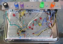
Emma ReezaFratZitz cb mod v0.1 breadboard 02.jpg

Build Docs Coming Soon...
 
Last edited:
I was wondering when you would get to this great 4069UBE based pedal.
It was your Double D build where I mentioned I had built the 6 knob version of this way back!
 
Version 1 was Volume, Tone, Gain & Bias
Version 2 is the one you built from.
I dont believe there was a 6 knob version, someone modified V2 to have a Mid pot & it does suffer from a bit of Volume loss but still has enough!
The Bias knob is suppose to mimic Class A or Class B type Amp depending which way it's rotated???
 
That's right, folks! I didn't know what at ReezaFratZitz was until Music6000 brought it to my attention.

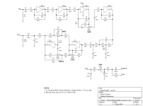
Here's my schematic. First two stages (U1F & U1E) are straightforward gain stages. C3 & R4 cut the bass below 400Hz. The 3rd & 4th stages (U1D & U1A) resemble the variable gain stages in a BluesBreaker. C7 & R9 roll-off more of the bass when GAIN is turned up. R11-R14 & C9-C11 roll-off some of the mids and treble after the distortion stages to smooth out the tone. The 5th stage (U1C) is another variable gain stage to control the output level. The last stage (U1B) is a modified Baxandall tone network. R22 & C17 roll-off a little more treble at the end. Other than deleting the emitter-follower input buffer, I didn't change anything up to C12. I reduced C12 to roll-off the bottom-end below 30Hz. I left the treble network intact, except I reduced R20 & R21 to give it more range and increased C15 to accommodate the addition of the bass network. I increased C17 slightly to accommodate the increased treble knob range. I changed the BIAS knob from B-taper to C-taper. The original designer, Emma, did a great job tuning the gain and freq response of each stage to make for nice, balanced tone. The distortion is always mellow and the note decay is smooth. In theory, this could be built with a CD4049 or two CD4007s. I haven't tried it yet. Highly recommended.

Emma ReezaFratZitz cb mod v0.1.png
 
Last edited:
Version 1 was Volume, Tone, Gain & Bias
Version 2 is the one you built from.
I dont believe there was a 6 knob version, someone modified V2 to have a Mid pot & it does suffer from a bit of Volume loss but still has enough!
The Bias knob is suppose to mimic Class A or Class B type Amp depending which way it's rotated???
My circuit is based on the version 1 schematic. The version 2 schematic I found had the BASS circuit done a completely different way. Tell me, does the MID control do anything in the 6-knob version? when I ran an LTSpice sim, it only moved the midrange a few dB up or down.

Saying the BIAS knob changes the tone from class-A to class-B is mostly sales jargon in my mind. With the BIAS turned up, there is less compression and the distortion is asymmetric, giving rise to more even-order harmonics and less odd-order harmonics. When BIAS is turned down, there is more compression and the distortion is more symmetric. Class-A amps have asymmetric clipping and less headroom. Class-B amps have mostly symmetric clipping and more headroom. Along with the GAIN knob, the BIAS knob allows one to fine-tune the compression and harmonic content. Turning the BIAS knob down also lowers the volume, but that can be compensated by turning up the LEVEL knob.
 
That's correct, The midrange knob is subtle with its response.
The Chap that designed V2 said with the Bass & Treble adjustment you can get the mids where they need to be!
Quote:
The 2. Generation ReezaFRATzitz is based on the best sounding Reeza RF-1 we could find. We added a low and high frequency control that gives you unprecedented midrange control.
Also added are the ingenious circuit: 'untrue bypass' that at Emma electronic is known as 'the overlord of the beast'. There are many myths about mechanical true bypass. often a true bypass is of no benefit to your signal chain. We chose the best solution for the ReezaFRATzitz RF-2.
 
Last edited:
Ah, yes, the buffered vs. true bypass debate!

To me, the best solution is to have a switch so one can choose whichever is best for their particular rig. Few pedals actually give you that option.

I would like to see the actual v2 schematic. Have not been able to find it on the web. As far as I can tell, the 6-knob schematic is someone's mod, not the Emma v2.
 
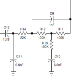
Uh-huh. R11-R13, C9 & C10 form a low-Q band reject filter (mid scoop). R14 & C11 form a low-pass filter.

The green trace is the freq response from U1-2 to the junction of C9, R12 & R14. As you can see, it's a broad mid scoop. The pink trace is the freq response from U1-2 to the junction of C11, C12 & R14. It shows the mid scoop and low-pass response together. What we end up with is basically a bass boost. It should be possible to realize that response with fewer parts, but it works so well as-is that I left it alone (at least for now).

1712169020893.png

The reason that circuit is there is to tame the higher-order harmonics and restore the bass/treble balance. The green trace is the response from the input to U1-2 (just after the last distortion stage). The pink trace is the response from the input to U1-6 (just before the tone stack). GAIN & LEVEL are at noon.

1712169817781.png
 
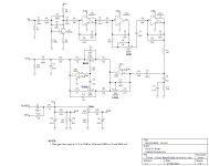
I analyzed the filter in post #8 and found that I could replicate it using two resistors (R11 & R12) and two capacitors (C9 & C10) as shown below. The response is identical within ±0.5dB. While I was at it, I considered the problem of obtaining low-noise CD4069 (or CD4049 for that matter). The only manufacturer producing CD4000-series parts these days is Texas Instruments. Their parts are known to be noisy. I've tested them in pedals. Surprisingly, the the current production CD4007s are not noisy. Go figure. The CD4007 contains three unbuffered inverters. One solution for building the ReezaFratZitz with currently available parts is to use two CD4007s to obtain the required six inverters. Another option is to use one CD4007 for three of the inverters and something else for the other three. Only three of the inverters in the ReezaFratZitz are used to make distortion: U1E, D & A in the schematic above. The other three run in linear mode because the signal level is low enough to prevent soft clipping. I replace the first stage (U1F) with a modified version of the first stage in a BMP (Q1, below). It has the same gain & freq response as the first stage above. I left the 2nd, 3rd & 4th stages alone; they are identical to the original circuit. I replaced the filter between the 4th and 5th stages as described above. I replace the level and tone control stages (U1C & D) with a TL072 (U2, below). Again, same gain & freq response as the last two stages above. Well, not quite. Since the TL072 has more headroom than the CD4007, I bumped up the available gain in the level stage by about 8dB so we can dial up a louder output if we want it. In other words, the LEVEL control now goes to 11. I also fiddled the impedances in the mid filter and tone network to take advantage of the opamp's lower output impedance. Most any opamps will work for the last two stages, they do not need to be FET-inut opamps. To accommodate the lower current draw of the CD4007, I modified the BIAS circuit a little bit. The breadboard matches the schematic except Q1 is a BC109C on the breadboard.

Emma ReezaFratZitz cb mod v2.1.png

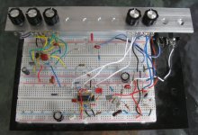
Knobs (L-R): LEVEL - BASS - TREBLE - GAIN - BIAS
The first stage is at the bottom right. The CD4007 is bottom center. The TL072 and tone network are at the upper left.
Emma ReezaFratZitz cb mod v2.1 breadboard 02.jpg
 
Back
Top