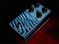
Chuck D. Bones
Circuit Wizard
It's been a year since I posted the All FET Tube Bender. I was not really satisfied with the tone. The BASS control did not cut enough bass when it was dialed-down. The JFET differential stage sound was a bit sterile. So I started over with the basic Tube Bender circuit and made mods from there. Here's the result. More range on the BASS control. Better TREBLE control range. A smooth transition from clean to fat to distorted. More headroom. Lower output impedance.
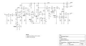
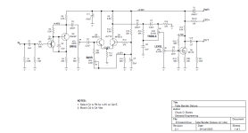
I went back to the Sziklai pair for the 1st stage, and replaced Q1 with a JFET. I could have left Q1 as a BJT, but JFETs are quieter, they have a higher input impedance, it takes one less resistor to bias the gate, and most importantly, I like JFETs. I set the gain just below 20dB so it would always run clean. I needed the lower output impedance of the Sziklai pair to drive the bass cut circuit. The bass cut is inspired by the Friedman TIGHT control. Plenty of range now! For the differential stage, I needed the high input impedance of a JFET, but I wanted the transfer function of a BJT diff pair. A couple of MPSA13 Darlington transistors was the answer. I retuned the TREBLE control to remove the mid scoop. The response is flat at 1:00. I moved the LEVEL control ahead of the last stage to maximize headroom. The MOSFET booster at the end ensures that we can get at least 6Vp-p output if we want it.
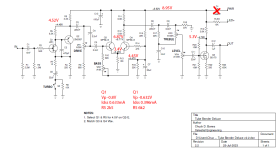
Voltages marked on the schematic are for reference only.
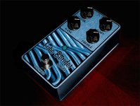
Knobs (L-R): LEVEL - TREBLE - BASS - DRIVE
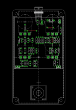
Q1 & Q2 on the far right, Q3 & Q4 in the middle, Q5 upper left.
I went back to the Sziklai pair for the 1st stage, and replaced Q1 with a JFET. I could have left Q1 as a BJT, but JFETs are quieter, they have a higher input impedance, it takes one less resistor to bias the gate, and most importantly, I like JFETs. I set the gain just below 20dB so it would always run clean. I needed the lower output impedance of the Sziklai pair to drive the bass cut circuit. The bass cut is inspired by the Friedman TIGHT control. Plenty of range now! For the differential stage, I needed the high input impedance of a JFET, but I wanted the transfer function of a BJT diff pair. A couple of MPSA13 Darlington transistors was the answer. I retuned the TREBLE control to remove the mid scoop. The response is flat at 1:00. I moved the LEVEL control ahead of the last stage to maximize headroom. The MOSFET booster at the end ensures that we can get at least 6Vp-p output if we want it.
Voltages marked on the schematic are for reference only.

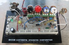
Knobs (L-R): LEVEL - TREBLE - BASS - DRIVE
Q1 & Q2 on the far right, Q3 & Q4 in the middle, Q5 upper left.


